Ingredient stirring device for brake pad production and use method of ingredient stirring device

A technology of stirring device and brake pad, which is applied to mixers with rotary stirring devices, accessories of mixers, chemical instruments and methods, etc., can solve the problems of insufficient mixing, low efficiency, poor stirring effect, etc., and improve the stirring effect. , High stirring efficiency, the effect of reducing stirring resistance

Inactive Publication Date: 2020-11-24
HENGYANG MAITE BRAKE SYST CO LTD
View PDF1 Cites 6 Cited by
  • Summary
  • Abstract
  • Description
  • Claims
  • Application Information

AI Technical Summary

Problems solved by technology

The stirring device in the above-mentioned patent has the following disadvantages: the stirring rod installed in the center is used for stirring. Since the friction material is different from the general liquid material, the stirring rod cannot ensure sufficient mixing, and the stirring effect is poor and the efficiency is low.

Method used


Image

  • Ingredient stirring device for brake pad production and use method of ingredient stirring device
  • Ingredient stirring device for brake pad production and use method of ingredient stirring device
  • Ingredient stirring device for brake pad production and use method of ingredient stirring device

Examples


Embodiment 1

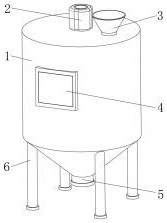
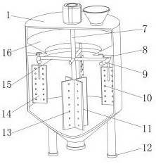
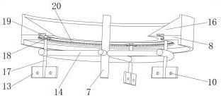
[0038] An ingredient mixing device for brake pad production, such as Figure 1-4As shown, it includes a main body 1, the top outer wall of the main body 1 is fixed with a stirring motor 2 by screws, and the top outer wall of the main body 1 is welded with a feed hopper 3, the bottom outer wall of the main body 1 is provided with a discharge port 5, and the stirring motor 2 The output end is rotatably connected with a stirring main shaft 7 through a coupling, and the outer wall of the stirring main shaft 7 is welded with the same annular support frame 9 through four support rods 15, and the inner wall of the annular support frame 9 is respectively rotatably connected with four circular support frames. Distributed first stirring mechanism, the bottom of the stirring main shaft 7 is also provided with a second stirring mechanism; the first stirring mechanism includes a first stirring blade 14 and a stirring secondary shaft 17, and the stirring secondary shaft 17 passes through a c...

Embodiment 2

[0044] An ingredient mixing device for brake pad production, such as Figure 5 , Image 6 As shown, in order to fully stir the material at the bottom of the main body 1; this embodiment makes the following improvements on the basis of embodiment 1: the second stirring mechanism is specifically a circumferentially distributed elastic plate 25, and one end of the elastic plate 25 is Welded to the peripheral outer wall of the bottom end of the stirring spindle 7, the elastic plate 25 has a whirlwind structure as a whole; by setting the elastic plate 25 with a whirlwind structure, it can better match the shape of the bottom of the main body 1, thereby improving the stirring of the bottom material of the main body 1 The effect is to strengthen the overall mixing degree and ensure the mixing efficiency.

[0045] In order to improve the stirring effect of the elastic plate 25, such as Image 6 As shown, the outer wall of one side of the elastic plate 25 is integrally provided with ...

Embodiment 3

[0049] A method of using the ingredient stirring device for brake pad production described in embodiment 1 or 2, such as Figure 1-6 shown, including the following steps:

[0050] S1: The user puts the material to be stirred into the main body 1 from the hopper 3, and ensures that the height of the material is lower than the height of the first guide seat 8;

[0051] S2: Set the rotation speed and working time of the stirring motor 2 through the control panel 4, and control the stirring motor 2 to stir;

[0052] S3: Take out the mixed material through the discharge port 5 after the stirring is completed.


PUM


Abstract

The invention discloses an ingredient stirring device for brake pad production and a use method of the ingredient stirring device, relates to the technical field of ingredient stirring devices for brake pad production and aims to improve the stirring effect. The device comprises a main body, wherein a stirring motor is fixed on the outer wall of the top of the main body through screws, a feeding hopper is welded on the outer wall of the top of the main body, a discharging port is formed in the outer wall of the bottom of the main body, an output end of the stirring motor is rotationally connected with a stirring spindle through a coupling, and the same annular support frame is welded on the circumferential outer wall of the stirring spindle through four support rods. The use method of thedevice comprises the following steps: a user puts a to-be-stirred material into the main body from the feeding hopper, and the height of the material is lower than that of a first guide seat. Multi-directional stirring is realized, the device is different from a common central rotating mechanism, the stirring effect of a second discharge hole is better, and the stirring efficiency is higher; and besides, by means of structures such as balls and the like, the rotating smoothness of a stirring countershaft is improved.

Description

technical field [0001] The invention relates to the technical field of an ingredient stirring device for brake pad production, in particular to an ingredient stirring device for brake pad production and a use method thereof. Background technique [0002] Friction material is a metal and non-metal composite material with high friction coefficient and high wear resistance made by powder metallurgy method; it is mainly used to manufacture various braking and transmission parts; in the production of brake pad friction material, It is often necessary to stir and mix it, and the general stirring device only stirs through the stirring shaft installed in the center, but because the friction material is different from the general liquid material, it cannot be guaranteed to be fully mixed through this type of device, and the stirring effect is poor ,low efficiency. [0003] After searching, the Chinese patent application number is CN201710219245.7, which discloses a batching stirring...

Claims


Application Information

Patent Timeline
Patent Type & Authority Applications(China)
IPC IPC(8): B01F7/30B01F15/00B01F15/02
CPCB01F27/054B01F27/11251B01F27/112B01F27/1162B01F27/213B01F27/2322B01F27/951B01F35/221422B01F35/22161B01F35/71731
Inventor 肖锋于海泉黄世成
Owner HENGYANG MAITE BRAKE SYST CO LTD
Why Eureka
Try Eureka