
Ash discharging device of quench pump station

The technology of a cleaning device and a pumping station is applied in the direction of cleaning methods and appliances, cleaning methods using tools, chemical instruments and methods, etc., which can solve the problems of high frequency of replacement of cleaning devices, high cost of use, and lack of self-cleaning functions. , to improve the efficiency and stability of use, and to avoid dust pollution

Active Publication Date: 2020-11-24
合肥源康信息科技有限公司
View PDF7 Cites 0 Cited by
  • Summary
  • Abstract
  • Description
  • Claims
  • Application Information

AI Technical Summary

Problems solved by technology

[0006] The purpose of the present invention is to provide a quick cooling pump station ash discharge device to solve the problem that the cleaning devices proposed in the above background technology are all installed on the bottom plate of the tank body, that is, located in the working chamber, which will cause the blockage generated by the quick cooling pump. The dust will fall on the cleaning device, and the cleaning device itself does not have self-cleaning function, so in actual work, the use efficiency of the cleaning device is not high, and because the main components are located in the working chamber of the quench pump, due to the The environment is harsh, so it may cause technical problems such as high frequency of replacement of cleaning devices and high cost of use

Method used


Image

  • Ash discharging device of quench pump station
  • Ash discharging device of quench pump station
  • Ash discharging device of quench pump station

Examples


Embodiment Construction

[0036] The following will clearly and completely describe the technical solutions in the embodiments of the present invention with reference to the accompanying drawings in the embodiments of the present invention. Obviously, the described embodiments are only some, not all, embodiments of the present invention. Based on the embodiments of the present invention, all other embodiments obtained by persons of ordinary skill in the art without creative efforts fall within the protection scope of the present invention.

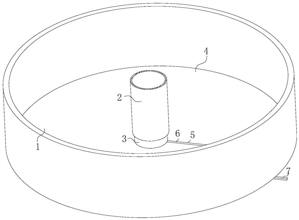
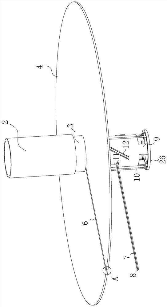
[0037] see Figure 1-9 , the present invention provides a technical solution: a quick cooling pumping station ash discharge device, including a tank wall 1, a bottom plate 4 and a connecting sleeve 2; The body is fixedly provided with a connection sleeve 2 (the connection sleeve 2 is fixed on the lower surface of the internal device of the pipe body, and can also be fixed on the bottom plate 4, depending on the internal structure of the different quench towers, it ...


PUM


Abstract

The invention relates to the field of ash removal of quench pumps, and discloses an ash discharging device of a quench pump station. The ash discharging device of the quench pump station comprises a tank wall, a bottom plate and a connecting sleeve. The bottom plate is fixedly arranged on the bottom side of the tank wall. The connecting sleeve is fixedly arranged on a tank body directly above themiddle position of the bottom plate. A sealing tube is slidably arranged in the connecting sleeve. An ash removal device is fixedly connected to the lower end of the sealing tube. A through hole is formed in the middle of the bottom plate. The bottom plate sleeves the ash removal device through the through hole. A penetrating ash trough is formed in the radial direction of the bottom plate. A sealing device is sealed on the ash trough. The device solves the technical problem that a traditional cleaning part is easily polluted by ash in the tank body.

Description

technical field [0001] The invention relates to the field of quick cooling pump ash removal, in particular to an ash discharge device for a quick cooling pump station. Background technique [0002] In the entire flue gas purification process, the wet method is irreplaceable, because while purifying the flue gas, it causes more serious water pollution and soil pollution, and the cost of dry method purification is very high. Therefore, most of the developed countries in the world currently The semi-dry method is used to purify the flue gas. The quenching tower is the crucial first ring in the semi-dry process. The quenching tower is also called the quenching pump station. The main function of the quenching tower is to quickly cool down the high-temperature flue gas to ensure that the bag filter Or electrostatic precipitator and deodorizing adsorber for flue gas temperature requirements, quenching tower is an indispensable device in any form of flue gas purification system, que...

Claims


Application Information

Patent Timeline
IPC IPC(8): B08B1/04
CPCB08B1/32
Inventor 奚邦建王勇陆永翠
Owner 合肥源康信息科技有限公司
Features
  • Generate Ideas
  • Intellectual Property
  • Life Sciences
  • Materials
  • Tech Scout
  • Unparalleled Data Quality
  • Higher Quality Content
  • 60% Fewer Hallucinations
Learn More