Grouting device for cement pipe production

A technology for cement pipes and connecting pipes, which is applied in the field of grouting devices for cement pipe production, can solve the problems of reducing the grouting efficiency of cement pipe molds, unable to adjust the discharge volume and discharge speed of a discharge cylinder, and achieve the effect of improving efficiency.

Inactive Publication Date: 2020-11-24
新邵县永沣水泥制品有限公司
View PDF0 Cites 1 Cited by
  • Summary
  • Abstract
  • Description
  • Claims
  • Application Information

AI Technical Summary

Problems solved by technology

[0003] The existing grouting device for cement pipe production cannot adjust the discharge volume and discharge speed of the discharge cylinder according to the diameter of the cement pipe mold to be poured when grouting the cement pipe mold, which reduces the need for cement pipes with different diameters. Mold Grout Efficiency

Method used


Image

  • Grouting device for cement pipe production
  • Grouting device for cement pipe production
  • Grouting device for cement pipe production

Examples


Embodiment Construction

[0020] In order to make the object, technical solution and advantages of the present invention clearer, the present invention will be further described in detail below in conjunction with the accompanying drawings and embodiments. It should be understood that the specific embodiments described here are only used to explain the present invention, not to limit the present invention.

[0021] In describing the present invention, it should be understood that the terms "length", "width", "upper", "lower", "front", "rear", "left", "right", "vertical", The orientation or positional relationship indicated by "horizontal", "top", "bottom", "inner", "outer", etc. are based on the orientation or positional relationship shown in the drawings, and are only for the convenience of describing the present invention and simplifying the description, rather than Nothing indicating or implying that a referenced device or element must have a particular orientation, be constructed, and operate in a ...


PUM


Abstract

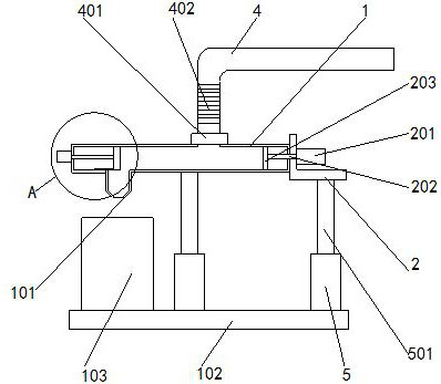
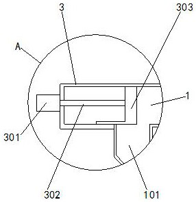
The invention belongs to the technical field of cement pipes, in particular to a grouting device for cement pipe production. The grouting device comprises a grouting cylinder, wherein a bottom plate is arranged below the grouting cylinder, a cement pipe mold is installed on the upper end surface of the bottom plate, a discharging cylinder communicates with the left side of the lower end surface ofthe grouting cylinder, an adjusting cylinder communicates with the left side of the grouting cylinder, a second air cylinder is installed on the left side of the adjusting cylinder, a second connecting rod is detachably connected to the output end of the second air cylinder, the right end of the second connecting rod penetrates through the adjusting cylinder and extends into the adjusting cylinder, an adjusting block is installed on the right side of the second connecting rod, a first air cylinder is installed on the right side of an L-connecting frame, a pushing block is installed on the left side of a first connecting rod, and a pipeline communicates with the upper end of the connecting pipe. Thus, when the cement pipe mold is grouted, the discharge volume and discharge speed of the discharging cylinder are conveniently adjusted according to the diameter of the to-be-grouted cement pipe mold, and the grouting efficiency of the cement pipe molds with different diameters is improved.

Description

technical field [0001] The invention relates to the technical field of cement pipes, in particular to a grouting device for cement pipe production. Background technique [0002] Cement pipes are also called cement pressure pipes and reinforced concrete pipes. They can be used as sewer pipes in urban construction, sewage, flood control and drainage, as well as water pipes and farmland wells used in some special factories and mines. They are generally divided into: flat reinforced concrete Cement pipes, flexible tongue and groove reinforced concrete pipes, socket reinforced concrete pipes, F-shaped steel socket cement pipes, flat ring interface cement pipes, tongue and groove cement pipes, etc., need to be put into cement pipe molds during the production process of cement pipes Pour cement mortar. [0003] The existing grouting device for cement pipe production cannot adjust the discharge volume and discharge speed of the discharge cylinder according to the diameter of the ce...

Claims


Application Information

Patent Timeline
Patent Type & Authority Applications(China)
IPC IPC(8): B28B13/02B28B17/00
CPCB28B13/02B28B17/0063
Inventor 廖受
Owner 新邵县永沣水泥制品有限公司
Why Eureka
Try Eureka