

A knitting machine based on the technology of preventing knitting thread breakage
A knitting machine and knitting thread technology, applied in the field of knitting machinery based on the technology of preventing knitting thread breakage, can solve problems such as difficulty in meeting usage requirements, low operating rate of knitting machinery, shutdown and wiring of knitting machinery, etc., so as to improve application convenience and improve Transferability, the effect of improving the driving rate
- Summary
- Abstract
- Description
- Claims
- Application Information
AI Technical Summary
Problems solved by technology
Method used
Image

Examples
Embodiment 1
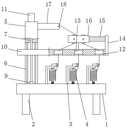
[0032] See Figure 1-3 , a knitting machine based on the technology of preventing knitting thread breakage, comprising a machine board 1, the bottom end of the machine board 1 is uniformly provided with several leg assemblies 2, and the top end of the machine board 1 is provided with a stand 5 and several wire rollers Frame assembly 3, all the wire roll frame assemblies 3 are arranged side by side in parallel, wire rolls 4 are installed on the wire roll frame assemblies 3, by setting the wire roll frame assemblies 3 side by side, it is convenient to centrally install or disassemble the wire rolls 4, and it is convenient to complete the alignment The installation of knitting thread raw materials or the disassembly of the alignment roller shell can realize fast replenishment of knitting raw materials;
[0033] The stand 5 is arranged on the left side of the line roller frame assembly 3, the stand 5 is a U-shaped structure, the top of the stand 5 is fixedly connected to the lifti...
Embodiment 2
[0037] See Figure 4 The difference from Embodiment 1 is that the elastic mechanism 15 includes a pneumatic cylinder 151 and two slide rods 152, and the two slide rods 152 are fixedly connected to the side ends of the vertical plate 14 near the stand 5, and the two slide rods 152 are symmetrically arranged on the front and rear sides of the vertical plate 14. The pneumatic cylinder 151 is fixedly connected to the stand 5, and the movable end of the pneumatic rod 153 on the pneumatic cylinder 151 runs through the vertical plate 14 and hangs in the air. The second guide assembly 16 includes a moving plate 161, the moving plate 161 is slidably connected to the two slide bars 152, the movable end of the air pressure rod 153 is fixedly connected to the moving plate 161, and the moving plate 161 is provided with a hole 162, the inner cavity of the through hole 162 is symmetrically provided with a second guide roller 163, and the second guide roller 163 is connected to the moving pla...
Embodiment 3
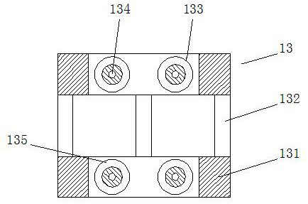
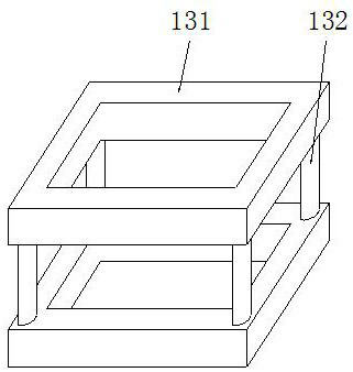
[0039] See Figure 5 The difference from Embodiment 1 is that the wire roll frame assembly 3 includes a roll frame 31, an upper top sleeve shaft 33 and a lower top sleeve shaft 34, the roll frame 31 is an L-shaped structure, and the roll frame 31 is fixedly installed on On the machine plate 1, the cross-sections of the upper top sleeve shaft 33 and the lower top sleeve shaft 34 are T-shaped structures, and the upper top sleeve shaft 33 is fixedly installed on the inner cavity top wall of the roller frame 31, and the lower top sleeve shaft 34 is fixed on the inner cavity top wall of the roller frame 31. The bottom end of the top sleeve shaft 34 is evenly provided with some telescopic rods 35, and the bottom end of the telescopic rods 35 is fixedly connected to the upper top of the machine plate 1. A pre-tension spring 36, the end of the pre-tension spring 36 is fixedly connected to the top of the machine plate 1, the wire roller 4 is installed between the upper top sleeve shaft...
PUM
 Abstract
Description
Claims
Application Information