LED energy-saving lamp tube with external breakage-proof structure

A technology of LED energy-saving lamps and lamp tubes, which is applied to parts of lighting devices, damage prevention measures of lighting devices, semiconductor devices of light-emitting elements, etc., and can solve the problems of easily broken lamp tubes and poor heat dissipation effect of shatterproof lamp tubes , to achieve the effect of good anti-shattering effect, stable protection and high control precision

Active Publication Date: 2020-11-24
江西瑞臻科技有限公司
View PDF6 Cites 0 Cited by
  • Summary
  • Abstract
  • Description
  • Claims
  • Application Information

AI Technical Summary

Problems solved by technology

[0003] The purpose of the present invention is to propose an LED energy-saving lamp tube with an external shatterproof structure to solve the technical problems in the prior art that the lamp tube is easily broken and some shatterproof lamp tubes have poor heat dissipation effect

Method used


Image

  • LED energy-saving lamp tube with external breakage-proof structure
  • LED energy-saving lamp tube with external breakage-proof structure
  • LED energy-saving lamp tube with external breakage-proof structure

Examples


Embodiment 1

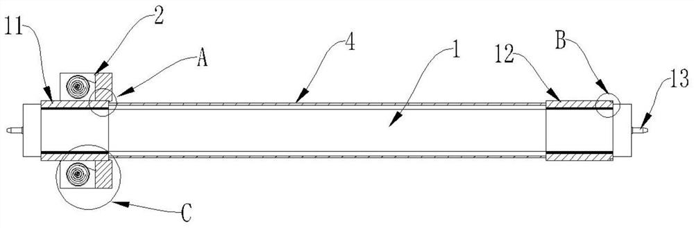
[0074] Further, as figure 1 with Figure 11 As shown, the diameter of the outer ring of the protection wire hiding part 22 is equal to the diameter of the outer ring of the protection wire tensioning part 23 .

[0075] In this embodiment, the outer diameters of the protection line hiding part 22 and the protection line stretching part 23 are the same, and the protection line hiding part 22 needs to accommodate the automatic winding structure 221 and the protection line 21 , so the thickness is greater than that of the protection line stretching part 23 . When the protection line 21 is crimped in the protection line hiding part 22 , the protection line stretching part 23 is in close contact with the protection line hiding part 22 . With such arrangement, it is convenient for the user to grasp the protective thread stretching member 23 when the protective thread 21 needs to be stretched and stretched.

Embodiment 2

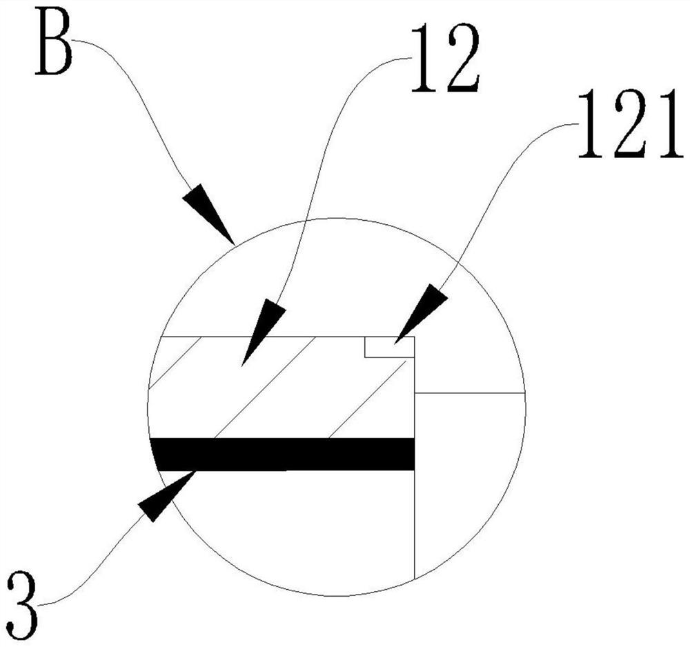
[0077] Such as Figure 12 As shown, the protection line hiding part 22 is provided with an annular accommodation cavity 222 on the side close to the protection line stretching part 23. When the protection line 21 is crimped in the protection line hiding part 22, the protection line The wire stretching member 23 is clamped in the annular accommodating cavity 222 .

[0078] Compared with Embodiment 1, in this embodiment, an annular accommodation cavity 222 is provided on the side of the protection line hiding part 22 close to the protection line tensioning part 23, and the outer diameter of the protection line tensioning part 23 is smaller than or equal to the inner diameter of the annular accommodation cavity 222 ; When the protection line 21 is crimped in the protection line hiding part 22, the protection line stretching part 23 is located in the annular accommodation cavity 222. Such arrangement can make the structure of the protection assembly 2 more compact. In order to f...

Embodiment 3

[0080] Such as Figure 13 As shown, the protective wire 21 includes an inner protective wire 211 and an outer protective wire 212, and the automatic winding structure 221 includes a first automatic winding structure 223 and a second automatic winding structure 224;

[0081] Both ends of the inner protection line 211 are respectively connected to the first automatic winding structure 223 and the protection line stretcher 23;

[0082] The outer protection line 212 is respectively connected to the second automatic winding structure 224 and the protection line tension member 23;

[0083] The second automatic thread winding structure 224 is located on the side of the first automatic thread winding structure 223 away from the center of the protection thread hiding part 22 .

[0084] Equivalently, there are two layers of protection lines 21 (inner protection line 211 and outer protection line 212) in a protection component 2, wherein the inner protection line 211 is close to the lam...


PUM


Abstract

The invention relates to the technical field of lighting equipment, in particular to an LED energy-saving lamp tube with an external breakage-proof structure, comprising: a lamp tube body and a protection assembly, wherein two ends of the lamp tube body are provided with a first lamp tube end cap and a second lamp tube end cap respectively; the protection assembly comprises a protection wire, a protection wire hiding part and a protection wire stretching part, and an automatic wire winding structure is arranged in the protection wire hiding part; one end of the protective wire is connected with the automatic wire winding structure, the other end of the protective wire is connected with the protective wire stretching part, and the protective wire hiding part sleeves the first lamp tube plug; when the protective wire stretching part sleeves the first lamp tube end cap, the protective wire is retracted in the protective wire hiding part. When the protective wire stretching part sleeves the second lamp tube end cap, the protective wire is pulled out and located on the outer side of the lamp tube body. The protection assembly is arranged, so that the energy-saving lamp tube can be prevented from being easily impacted by other objects in the carrying, taking and using processes, and the lamp tube is prevented from being broken.

Description

technical field [0001] The invention relates to the technical field of lighting equipment, in particular to an LED energy-saving lamp tube with an external shatterproof structure. Background technique [0002] The lamp tube is a very common lighting tool, and it is generally installed on the corresponding lamp holder when used. LED tubes, commonly known as straight tube lamps, are a substitute for traditional fluorescent tubes, which are reflected in two aspects of energy saving and environmental protection, so they are often called LED energy-saving lamps. The size and installation method are the same as traditional fluorescent lamps, but the principle of light emission is to use LED semiconductor chips to emit light. The shell of the LED energy-saving lamp tube is usually made of glass, and the glass is easily broken after being bumped or dropped. With the continuous development of science and technology, some shatterproof lamp tubes have appeared on the market. This k...

Claims


Application Information

Patent Timeline
Patent Type & Authority Applications(China)
IPC IPC(8): F21K9/272F21V23/06F21V27/00F21V17/16F21V17/12F21V15/04F21V15/00F21Y115/10
CPCF21K9/272F21V23/06F21V27/00F21V17/164F21V17/12F21V15/04F21V15/00F21Y2115/10
Inventor 万国华龚敬黄长贵罗洪来
Owner 江西瑞臻科技有限公司
Why Eureka
Try Eureka