
Light-load current detection device and method based on light-load mode of switching power supply

A technology of current detection device and switching power supply, which is applied in the direction of output power conversion device, high-efficiency power electronic conversion, electrical components, etc. It can solve the problems of high precision detection circuit, easy detection, light load efficiency loss, etc., to achieve Improve device battery life

Pending Publication Date: 2020-11-24
南京力源微电子有限公司
View PDF0 Cites 0 Cited by
  • Summary
  • Abstract
  • Description
  • Claims
  • Application Information

AI Technical Summary

Problems solved by technology

Sampling the inductor current requires the switching power supply to work in continuous conduction mode, resulting in a serious loss of light-load efficiency
With the popularization of various low-power devices, it has become an important requirement to maintain high efficiency by switching on the burst mode of the switching power supply under light load, and the simultaneous existence of light load detection and high efficiency has become a difficulty.
Moreover, light-load detection requires high precision of the detection circuit, and the smaller the set current, the easier it is to detect

Method used


Image

  • Light-load current detection device and method based on light-load mode of switching power supply
  • Light-load current detection device and method based on light-load mode of switching power supply
  • Light-load current detection device and method based on light-load mode of switching power supply

Examples


Embodiment Construction

[0024] The present invention will be further illustrated below in conjunction with the accompanying drawings and specific embodiments. It should be understood that the embodiments are only used to illustrate the present invention and are not intended to limit the scope of the present invention.

[0025] The present invention determines the load current by calculating the time interval of the light load mode on the basis of the existing switching power supply with the light load mode. In this way, the switching power supply can maintain high-efficiency burst mode and detect light-load current under light load.

[0026] Specifically, it is assumed that the light-load ripple in the burst mode of the switching power supply is Vr, and the target light-load current to be detected is set as I. The electric quantity charged on the output capacitor Cout in each interval is equal to the discharged electric quantity. Then there are:

[0027] Vr×Cout=I×T

[0028]

[0029] In this wa...


PUM


Abstract

The invention relates to a light-load current detection device and method based on a light-load mode of a switching power supply. The device comprises the switching power supply and a timing module. The switching power supply comprises a light load mode detection module and a switching power supply control module. The light load mode detection module compares the output voltage of the switching power supply with a reference voltage, and outputs a sleep signal to the switching power supply control module according to a comparison result so as to control the output of the output voltage of the switching power supply. The timing module receives the dormancy signal and outputs a light load current confirmation signal when the dormancy signal indicates that the switching power supply is in a light load mode for more than a preset time. According to the invention, no extra sampling resistor sampling circuit or packaging cost needs to be added, no dependence on the sampling circuit precisionis needed, smaller load current can be detected, the switching power supply is intermittently turned on, the equipment always works in a high-efficiency mode before dormancy, and the endurance of theequipment is improved.

Description

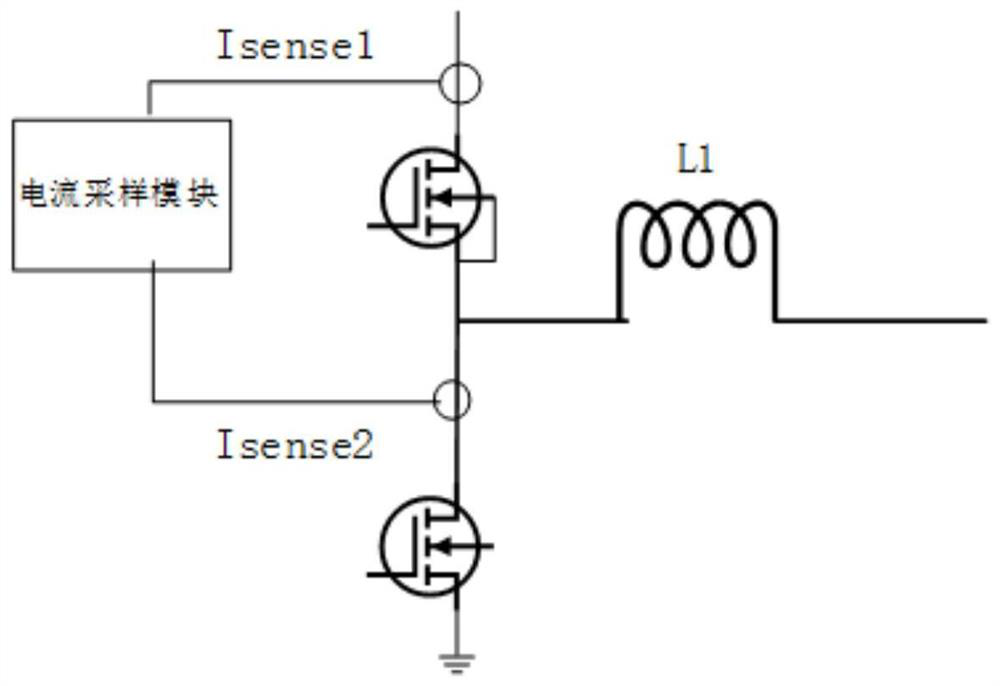
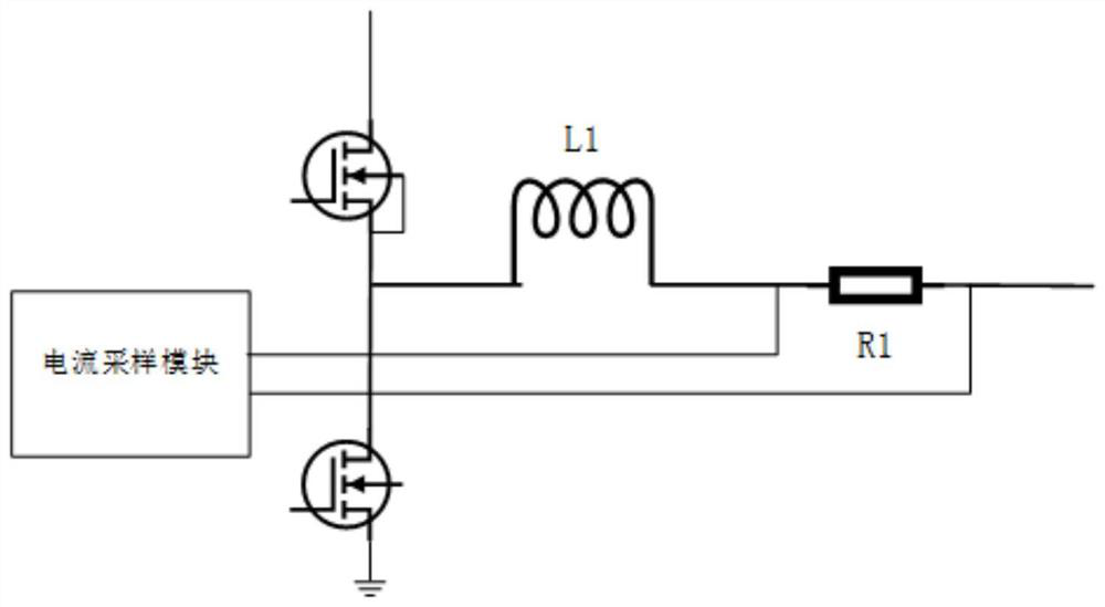
technical field [0001] The invention relates to a light-load current detection device and method, in particular to a light-load current detection device and method based on a light-load mode of a switching power supply. [0002] technical background [0003] Light-load mode is a mode in which the switching power supply enters the mode of turning off the power tube for a period of time and then turning on the power tube in order to improve the efficiency of small current output. Intermittent switching will generate light-load ripple, such as figure 1 shown. Light-load current detection is to judge that the load current is less than a certain value and give a signal, and the system will automatically shut down or take other actions accordingly. Portable devices usually need to sleep to save power after detecting light load current. Switching power supply light-load detection is a difficult point in design. One of the traditional detection methods is to connect a resistor in s...

Claims


Application Information

Patent Timeline
IPC IPC(8): H02M1/088
CPCH02M1/088H02M1/0009H02M1/0032Y02B70/10
Inventor 厉伟杰苏淼罗鑫王耀桢
Owner 南京力源微电子有限公司
Learn More