Power saver with improved current path and integrated power saver with the same

A current channel and power saving technology, applied to circuit devices, electrical components, AC network circuits, etc., can solve problems such as high maintenance costs, easy failures, manual intervention, etc., to improve power saving efficiency, reduce load current, The effect of improving power transmission efficiency

Inactive Publication Date: 2016-12-07
吴刚
View PDF3 Cites 0 Cited by
  • Summary
  • Abstract
  • Description
  • Claims
  • Application Information

AI Technical Summary

Problems solved by technology

[0003] At present, the power saving devices commonly used in the world are third-generation power saving devices, which are series-type frequency conversion devices and need to be connected in series with each electrical equipment. This method has several defects. First, , the user needs to change the operating habits and ways of using electricity. Second, if this series frequency conversion device fails, it will cause the user's equipment to fail to operate normally and affect normal production, so manual intervention is necessary. Third , this kind of serial frequency conversion device not only consumes a lot of power, but also has complex circuits, which is not only prone to failure, but also has high user input costs and high maintenance costs in the later period, resulting in low economic benefits
[0004] Moreover, the general power saver mostly adopts the method of lowering the voltage to achieve the purpose of saving electricity, but for precision machines that are sensitive to voltage, this method is easy to cause damage to the machine, such as the lighting field, etc.

Method used


Image

  • Power saver with improved current path and integrated power saver with the same
  • Power saver with improved current path and integrated power saver with the same
  • Power saver with improved current path and integrated power saver with the same

Examples


Embodiment Construction

[0013] The present invention will be further described in detail below in conjunction with the accompanying drawings and embodiments.

[0014] In the interaction force between electrons, when the attractive force between electrons is greater than the repulsive force between electrons, there will be a mutual attractive force between two electrons, so that the two electrons form a pair of electron pairs (Cooper pair Cooper pair) internal structure. When the current flows through the current saver, if the energy increase of the electron pair (Cooper pair) is less than the energy gap, there will be no excited state, so the electrons will not scatter, and the current will continue to pass. Therefore, through the radiation method in the energy transmission method, these wasted currents are re-input into the power line, and a certain torque is maintained to improve the current and save electricity.

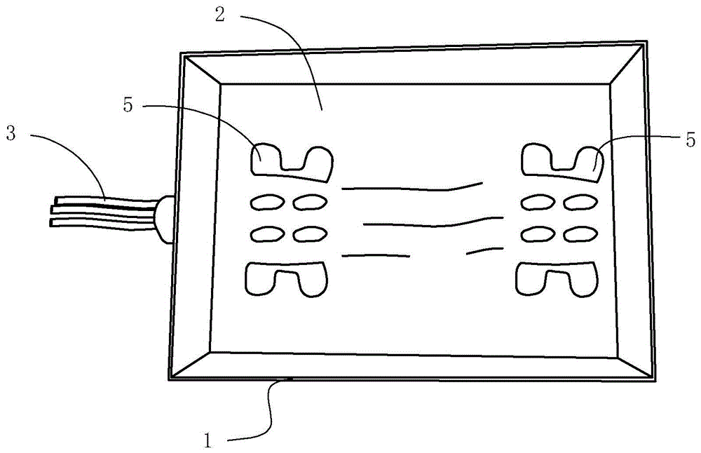
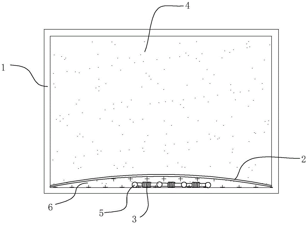
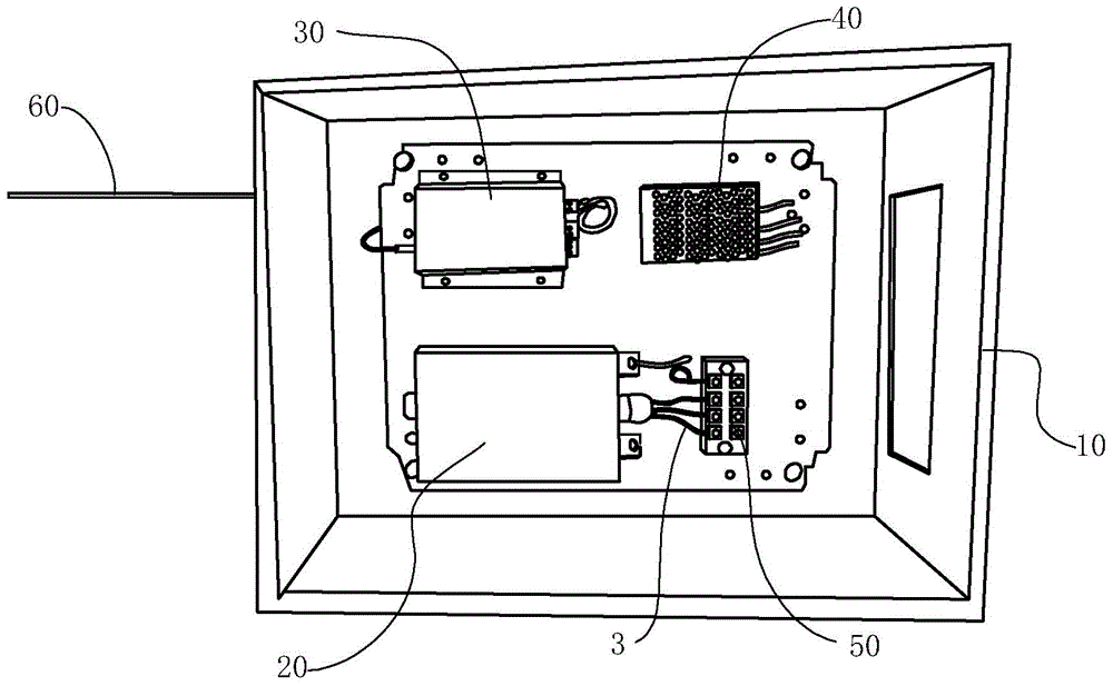
[0015] The power saver of the embodiment of the present invention, such as figure ...


PUM


Abstract

A electricity-saving appliance for improving a current channel comprises a housing, wherein at least two ceramic reels parallelly arranged at intervals are arranged at the bottom of the housing, at least two lead wires are inserted into the bottom of the housing and sequentially wounded on the ceramic reels, the lead wires on each ceramic reel are winded at intervals, insulation layers are cover the upper portions of the ceramic reels and the lead wires, ceramic particles are filled between the insulation layers and the bottom of the housing, and fill materials are filled between the upper portions of the insulation layers and the housing. The electricity-saving appliance and a comprehensive electricity-saving device provided with the electricity-saving appliance improve power transmission efficiency to improve the electricity-saving efficiency under the condition that voltage is not changed by decreasing load current in a current channel improving mode, are suitable for various electrical appliances, are especially used in certain production fields needing high-voltage power and especially can produce remarkable electricity-saving effect.

Description

technical field [0001] The invention relates to a power saver and a comprehensive power saver with the saver. Background technique [0002] In the power grid of end users, there are a large number of transient currents, and transient currents are a kind of transient distortion of current and voltage in sine wave AC circuits, and surges and harmonics are their main manifestations. The main characteristics of distortion are ultra-high voltage, ultra-high speed, and ultra-high frequency. Ultra-high voltage means that the transient peak is 2-50 times higher than the normal voltage amplitude, ultra-high speed means that the transient peak occurs in a very short period of time, and ultra-high frequency means that the activity of the transient peak is very frequent. [0003] At present, the power saving devices commonly used in the world are third-generation power saving devices, which are series-type frequency conversion devices and need to be connected in series with each electr...

Claims


Application Information

Patent Timeline
Patent Type & Authority Patents(China)
IPC IPC(8): H02J3/00
CPCH02J3/00
Inventor 吴刚徐振沈国柱
Owner 吴刚
Why Eureka
Try Eureka