Unmanned aerial vehicle motor dragging method and system

A technology of dragging system and motor, applied in the field of unmanned aerial vehicle, can solve the problems of difficult debugging, long time for motor open-loop dragging, easy to lose steps when dragging, etc. long effect

Inactive Publication Date: 2020-11-24
丰翼科技(深圳)有限公司
View PDF3 Cites 0 Cited by
  • Summary
  • Abstract
  • Description
  • Claims
  • Application Information

AI Technical Summary

Problems solved by technology

Among them, the V / F dragging capacity is very poor, the dynamic performance is poor, and it is difficult to debug. Not suitable for UAV motor drag
Therefore, the motor of the UAV can be dragged by I / F. The setting of the startup acceleration is very critical. If the acceleration is too small, the open-loop dragging time of the motor will be longer. If the acceleration is too high, it will easily fail to start.
[0004] In the existing I / F dragging technology, the acceleration value is a fixed value, and this method has the problem of long dragging time

Method used


Image

  • Unmanned aerial vehicle motor dragging method and system
  • Unmanned aerial vehicle motor dragging method and system
  • Unmanned aerial vehicle motor dragging method and system

Examples


Embodiment Construction

[0028] The application will be further described in detail below in conjunction with the accompanying drawings and embodiments. It should be understood that the specific embodiments described here are only used to explain related inventions, rather than to limit the invention. It should also be noted that, for ease of description, only parts related to the invention are shown in the drawings.

[0029] It should be noted that, in the case of no conflict, the embodiments in the present application and the features in the embodiments can be combined with each other. The present application will be described in detail below with reference to the accompanying drawings and embodiments.

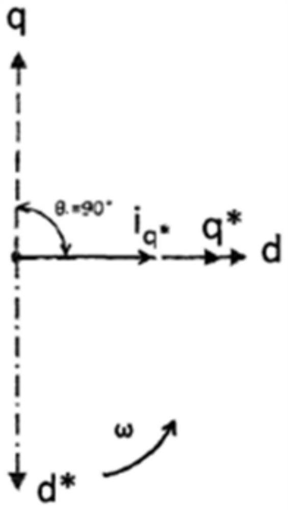
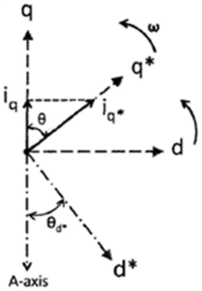
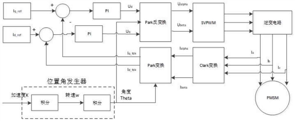
[0030] One of the embodiments of the present invention is, please refer to image 3 and 4 , UAV motor dragging method of the present invention, comprises the following steps:

[0031] Input the first current vector to the stator winding of the motor, the first quadrature axis current value of th...


PUM


Abstract

The invention discloses an unmanned aerial vehicle motor dragging method and system, and the method comprises the following steps: inputting a first current vector to a motor stator winding, enablinga first direct-axis current value of the first current vector to be 0, and enabling a first quadrature-axis current value of the first current vector to be a first preset value; according to the acceleration of the motor rotor, obtaining a rotor position angle, and increasing the acceleration from 0 to a second preset value at a constant speed; collecting three-phase current of the motor, and obtaining a second direct-axis current value and a second quadrature-axis current value according to the three-phase current and the rotor position angle; comparing and adjusting the second direct-axis current value with a given direct-axis current value to obtain a direct-axis voltage value, and comparing and adjusting the second quadrature-axis current value with a given quadrature-axis current value to obtain a quadrature-axis voltage value; obtaining a three-phase input voltage signal according to the direct-axis voltage value, the quadrature-axis voltage value and the rotor position angle; and driving the motor to rotate according to the three-phase input voltage signal, so that the dragging time can be effectively shortened.

Description

technical field [0001] The present invention generally relates to the field of unmanned aerial vehicles, specifically relates to the field of unmanned aerial vehicle motors, and in particular relates to a method and system for dragging an unmanned aerial vehicle motor. Background technique [0002] Due to the particularity of its structure, the UAV motor cannot use sensors to feed back the motor rotor position angle, and can only use sensorless control technology to feed back the motor rotor position angle; at the same time, because the salient polarity of the motor is relatively weak, it can only be used The rotor position observation technology based on the back electromotive force is used to detect the position of the motor rotor; on the other hand, since the back electromotive force of the motor is very small when the motor is at zero or very low speed, the UAV can only be driven by the open-loop dragging technology first. After the motor is dragged to a certain speed, t...

Claims


Application Information

Patent Timeline
IPC IPC(8): H02P6/21H02P21/34
CPCH02P6/21H02P21/34
Inventor 李林军
Owner 丰翼科技(深圳)有限公司
Why Eureka
Try Eureka