Efficient electromechanical monitoring device for expressway tunnel

A technology for highways and monitoring devices, applied to camera bodies, TVs, cameras, etc., can solve problems such as inconvenient maintenance and dead spots in monitoring, and achieve the effects of avoiding blockage, ensuring stable operation, and promoting flow exchange

Active Publication Date: 2020-11-24
高世君 +2
View PDF9 Cites 8 Cited by
  • Summary
  • Abstract
  • Description
  • Claims
  • Application Information

AI Technical Summary

Problems solved by technology

[0005] The purpose of the present invention is to provide a high-efficiency expressway tunnel electromechanical monitoring device with high monitoring efficiency, good effect and easy maintenance for the above-mentioned problems of monitoring dead angle and inconvenient maintenance

Method used


Image

  • Efficient electromechanical monitoring device for expressway tunnel
  • Efficient electromechanical monitoring device for expressway tunnel
  • Efficient electromechanical monitoring device for expressway tunnel

Examples


Embodiment 1

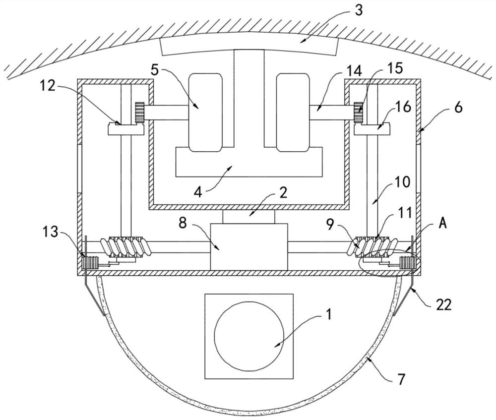
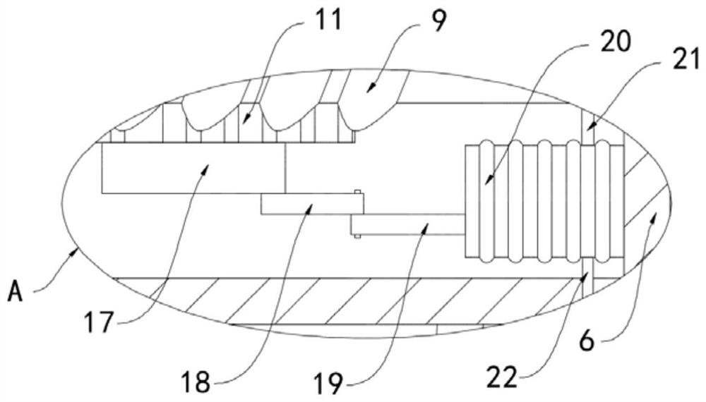
[0023] like Figure 1-2 As shown, a high-efficiency expressway tunnel electromechanical monitoring device includes a camera 1, a central controller 2 and a fixed plate 3. The fixed plate 3 is installed on the top surface of the tunnel and extends longitudinally along the tunnel. The lower surface of the fixed plate 3 is welded with an inverted The T-shaped slide rail 4, the two sides of the T-shaped slide rail 4 are rollingly connected with the traveling wheels 5, the bottom of the T-shaped slide rail 4 is provided with a U-shaped housing 6, and the lower surface of the U-shaped housing 6 is fixedly connected with an anti- Dust cover 7, dust cover 7 is a hemispherical glass cover, is convenient for camera 1 to rotate and shoot at multiple angles in dust cover 7, camera 1 is installed in dust cover 7, and the inner bottom surface of U-shaped housing 6 is equipped with biaxial The motor 8, the camera 1 and the biaxial motor 8 are all electrically connected to the central control...

Embodiment 2

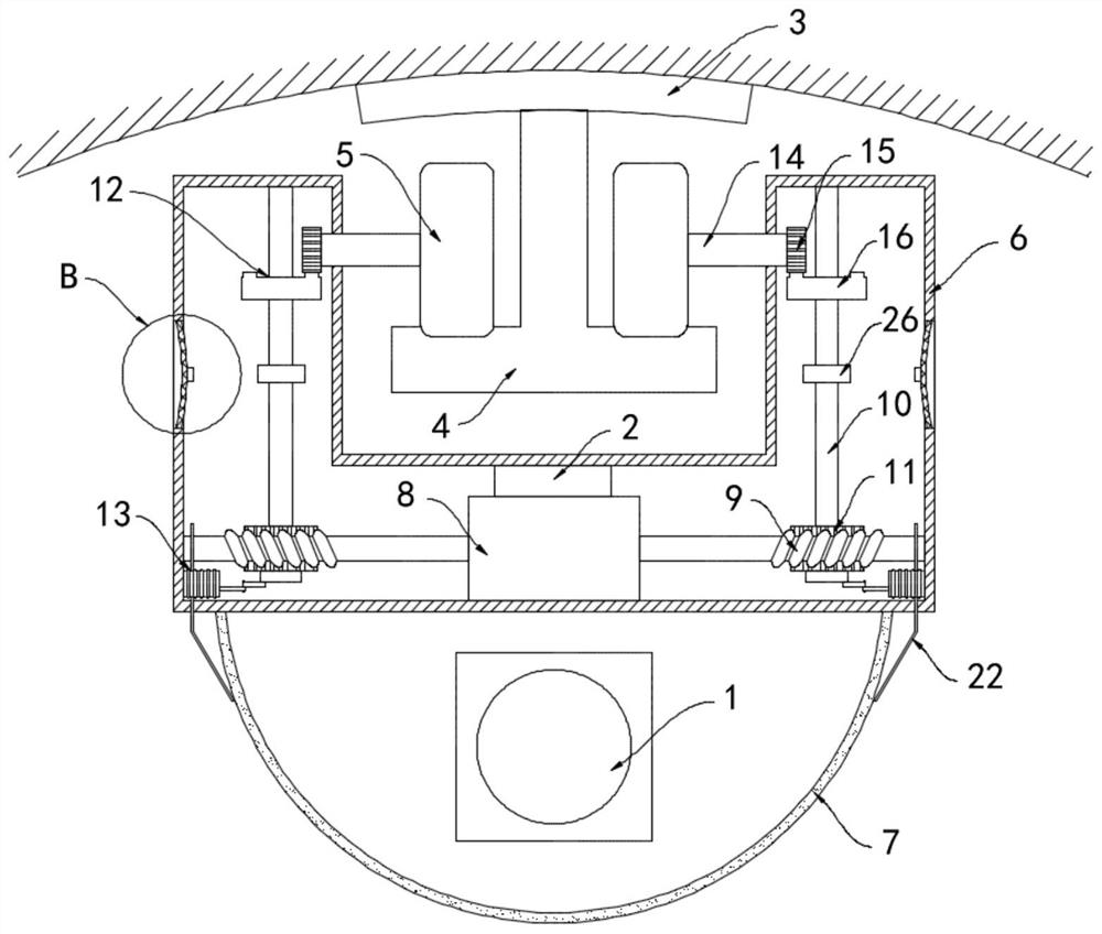
[0029] like Figure 3-4 As shown, the difference between this embodiment and Embodiment 1 is that: the side walls on both sides of the U-shaped housing 6 are provided with an air inlet 23, and a dust filter 24 is installed in the air inlet 23, and the dust filter 24 can be Filter the dust in the air, and the dust filter net 24 is woven by metal wire, has good deformability, is fixedly connected with the magnet block 25 on the side wall of the dust filter net 24, and is fixedly sleeved with the permanent magnetic ring 26 outside the rotating shaft 10, permanent The magnetic ring 26 is made up of two semi-annular magnets with opposite magnetic poles. During the rotation of the permanent magnetic ring 26 with the rotating shaft 10, the two semi-annular magnets with opposite magnetic poles are alternately close to or far away from the magnet block 25, that is, the permanent magnetic ring 26 is periodically The changing attractive and repulsive forces drive the magnet block 25 to a...


PUM


Abstract

The invention belongs to the technical field of electromechanical monitoring, in particular to an efficient electromechanical monitoring device for expressway tunnel. The device comprises a camera, acentral controller and a fixed plate, the fixed plate is installed on the top face of the tunnel and extends in the longitudinal direction of the tunnel, an inverted-T-shaped sliding rail is welded tothe lower surface of the fixed plate, travelling wheels are connected to the two sides of the T-shaped sliding rail in a rolling mode, a U-shaped shell is arranged below the T-shaped sliding rail, adustproof cover is fixedly connected to the lower surface of the U-shaped shell, the camera is installed in the dustproof cover, a double-shaft motor is installed on the inner bottom face of the U-shaped shell, and worms are coaxially and fixedly connected to output shafts at the two ends of the double-shaft motor. The monitoring device can patrol back and forth in the tunnel, dead-corner-free monitoring in the tunnel can be achieved without arranging a plurality of monitoring devices, the cost is reduced, the monitoring efficiency is greatly improved, accident rescue and traffic organizationin the tunnel are facilitated, and safe and stable operation of the tunnel is facilitated.

Description

technical field [0001] The invention belongs to the technical field of electromechanical monitoring, and in particular relates to an efficient electromechanical monitoring device for expressway tunnels. Background technique [0002] With the continuous development and improvement of the transportation system, there are more and more expressways. The development and construction of mountainous expressways is a major trend in the development of expressways in the future. The corresponding expressway tunnel mechanical and electrical engineering construction planning scale is also increasing. Monitoring plays a vital role in the daily operation and management of tunnels. [0003] Due to the narrow and long space of the expressway tunnel, the monitoring range of the monitoring device is limited, and there are a large number of monitoring dead spots. Once a traffic accident occurs, it is difficult for the monitoring device to quickly find the accident, and it is difficult to rescu...

Claims


Application Information

Patent Timeline
Patent Type & Authority Applications(China)
IPC IPC(8): H04N5/225G03B17/55G03B17/56F16M13/02B08B5/02B01D46/42B01D46/12
CPCG03B17/55G03B17/561F16M13/02B08B5/02B01D46/103B01D46/12B01D46/60B01D46/74H04N23/52H04N23/50
Inventor 高世君张姣平魏涛
Owner 高世君
Why Eureka
Try Eureka