An autonomous security control method for space optical relative measurement equipment

A technology of relative measurement and space optics, which is applied in the direction of TV, color TV parts, TV system parts, etc. It can solve problems such as damage to the lens, detection components, endangering product safety, and camera failure to work normally, so as to achieve a clear principle , to ensure work safety, to achieve convenient results

Active Publication Date: 2022-01-28
SHANGHAI AEROSPACE CONTROL TECH INST
View PDF0 Cites 0 Cited by
  • Summary
  • Abstract
  • Description
  • Claims
  • Application Information

AI Technical Summary

Problems solved by technology

When the sun enters the sun protection angle, not only the camera cannot work normally, but also damage the lens, detection components, etc., endangering product safety

Method used


Image

  • An autonomous security control method for space optical relative measurement equipment

Examples


Embodiment Construction

[0019] The present invention will be further elaborated below by describing a preferred specific embodiment in detail in conjunction with the accompanying drawings.

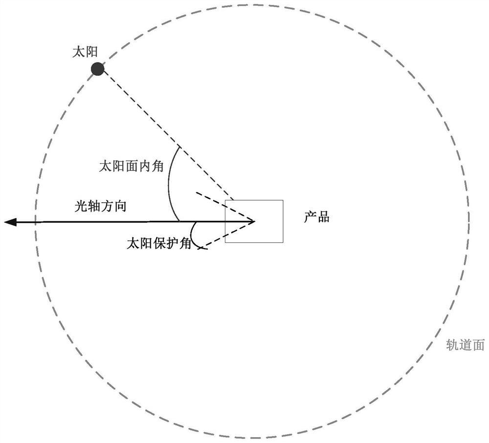
[0020] Such as figure 1 As shown, it is a schematic diagram of an autonomous safety control method for a spatial optical relative measurement device according to the present invention. In this embodiment, the spatial optical relative measurement device includes an optical camera.

[0021] Specifically, the autonomous safety control method of the space optical relative measurement equipment includes:

[0022] S1. Determine the relative position of the sun on the orbital plane of the space optical relative measuring equipment, expressed by the inner angle of the sun plane. The inner angle of the solar plane represents the position of the sun on the orbital plane, and at this time, the optical axis of the optical camera in the space optical relative measuring device is at zero position.

[0023] S2. Calculating th...


PUM


Abstract

The invention discloses an autonomous safety control method for space optical relative measurement equipment, the method comprising: S1, determining the relative position of the sun on the orbital plane of the space optical relative measurement equipment, represented by the inner angle of the sun surface; S2, calculating the space optical relative measurement The included angle between the optical axis of the device and the inner angle of the solar surface in the step S1 is represented by the sun incidence angle; S3, according to the relationship between the sun incidence angle and the solar protection angle threshold of the space optics relative measurement device , execute the corresponding mode state. Its advantages are: the method rationally uses the relationship between the inner angle of the solar surface, the solar incident angle and the threshold value of the solar protection angle, and satisfies the requirements for the safe operation of the space relative measurement equipment in orbit. Rail work can ensure the safety of the space relative to the measuring equipment.

Description

technical field [0001] The invention relates to the field of safe operation of space orbits, in particular to an autonomous safety control method for space optical relative measuring equipment, so as to ensure product safety during orbital operation. Background technique [0002] New requirements such as binary star formation, satellite constellation, and space security have promoted the development of inter-satellite relative measurement technology. A variety of inter-satellite relative measurement products, such as microwave radar, photoelectric combination, and laser radar, are emerging and have been successfully used in orbit. [0003] Usually space optical relative measurement equipment includes photoelectric combination, binocular camera and other products with optical camera as the main body. Due to its detection system, the most important influence of the camera during its work in space is the sun. Space cameras have an important indicator: the sun protection angle...

Claims


Application Information

Patent Timeline
Patent Type & Authority Patents(China)
IPC IPC(8): H04N5/232
CPCH04N23/667H04N23/695
Inventor 张朝兴邵志杰孙尚戴维宗王静吉袁彦红张小伟
Owner SHANGHAI AEROSPACE CONTROL TECH INST
Why Eureka
Try Eureka