
Signal transmission device

A signal transmission and antenna module technology, applied in transmission systems, antenna grounding devices, deicing/drying devices, etc., can solve the problem of uneven radiation field patterns of signal transmission devices, unable to provide signal transmission effects, and affect the signal transmission effect of antenna modules. and other problems to achieve the effect of reducing signal interference and improving heat dissipation.

Active Publication Date: 2020-11-24
WISTRON NEWEB
View PDF3 Cites 1 Cited by
  • Summary
  • Abstract
  • Description
  • Claims
  • Application Information

AI Technical Summary

Problems solved by technology

However, limited by the interference of the components around the antenna module, the radiation pattern of the signal transmission device is not uniform, which cannot provide a good signal transmission effect
Especially, with the development of 5G technology, when the frequency of the wireless signal is at a high frequency (for example, 28GHz and 39GHz), any element located in the radiation field may seriously affect the signal transmission effect of the antenna module

Method used


Image

  • Signal transmission device
  • Signal transmission device
  • Signal transmission device

Examples


Embodiment Construction

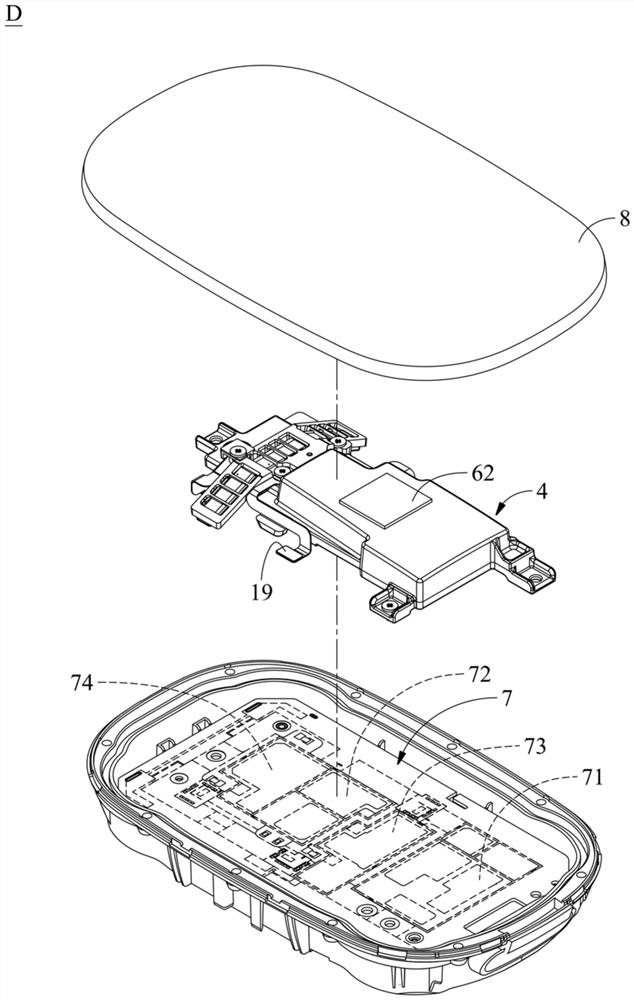
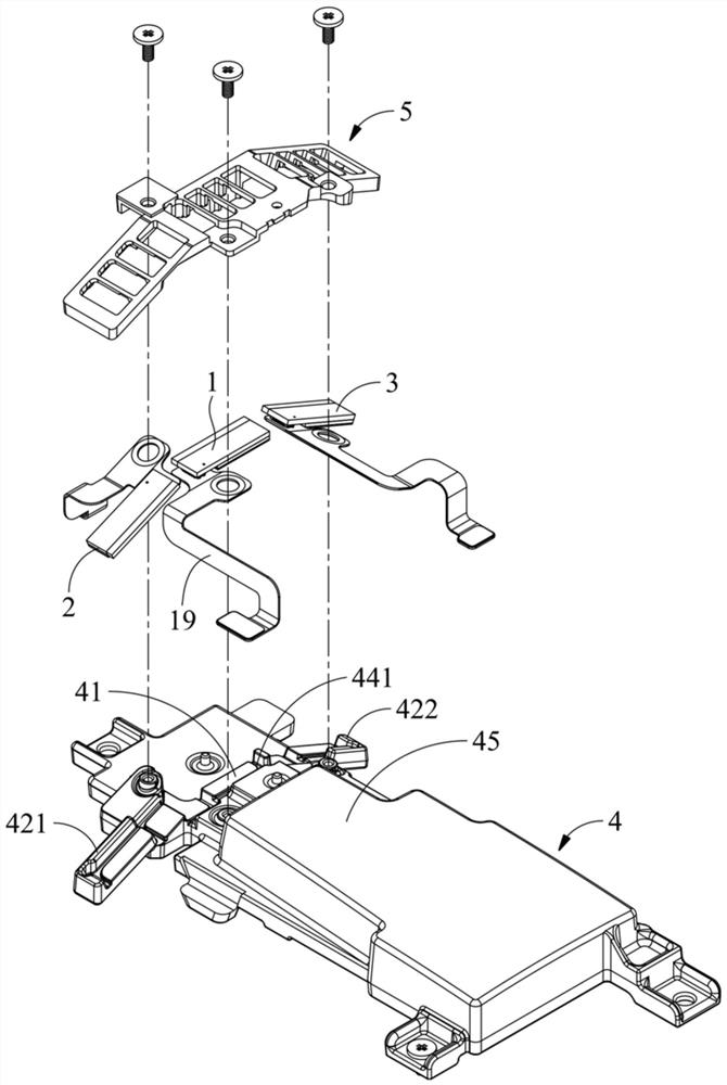
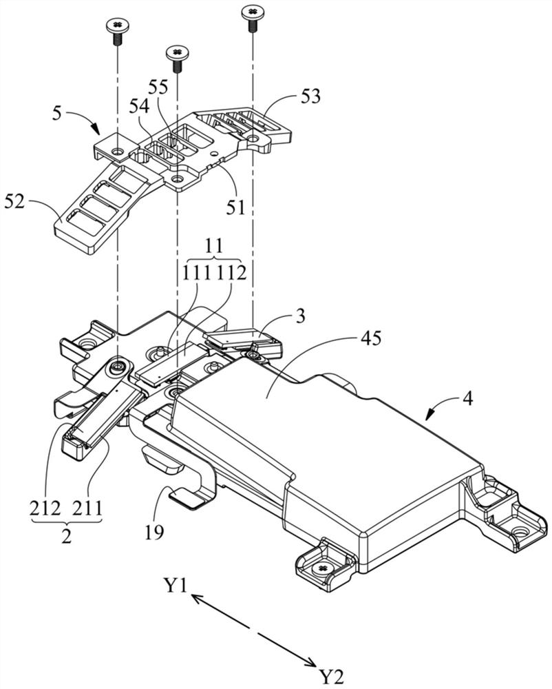
[0054] figure 1 An exploded view of a signal transmission device D according to an embodiment of the present invention is shown. figure 2 An exploded view of main components of a signal transmission device D according to an embodiment of the present invention is shown. Figure 3A as well as Figure 3B The assembly situation of the main components of the signal transmission device D according to the embodiment of the present invention is shown. collocation reference figure 1 , figure 2 , Figure 3A as well as Figure 3B , In one embodiment, the signal transmission device D includes a heat dissipation component 4 , a first antenna module 1 and a positioning cover 5 . The first antenna module 1 is disposed on the heat dissipation component 4 . The positioning cover 5 is fixed on the heat dissipation component 4, wherein the first antenna module 1 is located between the positioning cover 5 and the heat dissipation component 4, and the positioning cover 5 is suitable for r...


PUM


Abstract

Signal transmission device. The signal transmission device comprises a heat dissipation part, a first antenna module and a positioning cover. The first antenna module is arranged on the heat dissipation component and is in thermal connection with the heat dissipation component; the positioning cover is fixed on the heat dissipation component; wherein the first antenna module is clamped between thepositioning cover and the heat dissipation component; the positioning cover is suitable for limiting the first antenna module and comprises a plurality of positioning cover openings and a plurality of separation ribs, at least part of the positioning cover openings correspond to the first antenna module, and the separation ribs define the positioning cover openings in a separated mode. Accordingto the signal transmission device provided by the invention, the first antenna module is arranged on the heat dissipation component; the heat dissipation component is partially located between the first antenna module and the main circuit board, signal interference of the main circuit board to the first antenna module can be reduced, heat generated by the first antenna module can be directly led out and dissipated through the heat dissipation component, and therefore a good heat dissipation effect can be provided.

Description

technical field [0001] The invention relates to a signal transmission device, in particular to a signal transmission device with a relatively uniform radiation field type. Background technique [0002] In the known signal transmission device, the antenna module is arranged on the printed circuit board and located at the edge of the printed circuit board. However, limited by the interference of components around the antenna module, the radiation pattern of the signal transmission device is not uniform, which cannot provide a good signal transmission effect. Especially, with the development of 5G technology, when the frequency of the wireless signal is at a high frequency (for example, 28GHz and 39GHz), any element located in the radiation pattern may seriously affect the signal transmission effect of the antenna module. [0003] Therefore, it is necessary to provide a signal transmission device to solve the above problems. Contents of the invention [0004] Embodiments of...

Claims


Application Information

Patent Timeline
Patent Type & Authority Applications(China)
IPC IPC(8): H05K7/02H05K7/20H01Q1/02H01Q1/38H01Q1/48H01Q1/52H01Q21/00H01Q21/08H04B1/40
CPCH01Q1/02H01Q1/38H01Q1/48H01Q1/52H01Q1/521H01Q21/00H01Q21/08H04B1/40H05K7/023H05K7/2039
Inventor 陈思源吕曼宁邢琼雯林亦杰
Owner WISTRON NEWEB
Learn More