Device for machining thin-wall blind hole slender shaft

A slender shaft and blind hole technology, applied in the field of machining, can solve the problems of complex end structure, laborious insertion and removal, and high sealing structure requirements, so as to reduce the man-hours required for grinding, improve production efficiency, and improve grinding. The effect of cutting parameters

Active Publication Date: 2020-11-27
CHINA HANGFA SOUTH IND CO LTD
View PDF10 Cites 0 Cited by
  • Summary
  • Abstract
  • Description
  • Claims
  • Application Information

AI Technical Summary

Problems solved by technology

[0005] However, due to the differences in the profiles of the outer circular surfaces of shaft parts with similar blind hole structures of different aero-engines, in the production process, for different similar shaft parts with the same inner diameter, if the 201910997022.2 provided For the mandrel, the applicant found that chatter would occur during processing, which would seriously affect the product qualification rate
In addition, when using the mandrel provided by 201910997022.2, it is laborious to insert and remove due to the interference fit
[0006] In order to solve the above problems, the applicant provided a technical solution in the invention patent application titled "A Blind Hole Slender Shaft Inner Supporting Method" filed on the same day as this application, by providing a set in the inner cavity of the part that can The structure of inflating the inner cavity, so that the inner cavity of the part not only has a support structure that expands after inflation, but also maintains a certain pressure (2.5-3.5bar) in the entire inner cavity, thereby forming an internal support for the part and ensuring the safety of the part during processing. Support strength, but because the solution needs to seal the inner cavity, it has higher requirements for the sealing structure of the end, resulting in a more complicated structure of the end

Method used


Image

  • Device for machining thin-wall blind hole slender shaft
  • Device for machining thin-wall blind hole slender shaft
  • Device for machining thin-wall blind hole slender shaft

Examples


Embodiment Construction

[0031] In order to have a clearer understanding of the technical features, purposes and effects of the present invention, the specific implementation manners of the present invention will now be described with reference to the accompanying drawings. Wherein, the same parts adopt the same reference numerals.

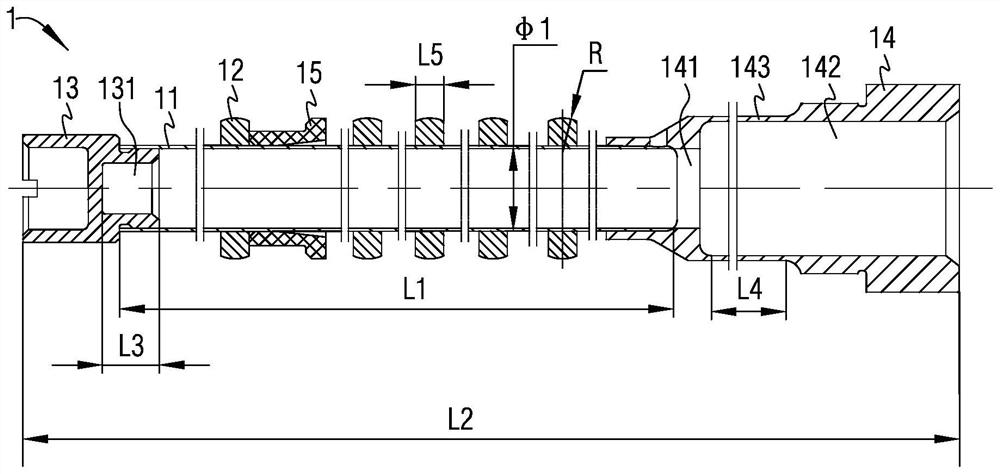
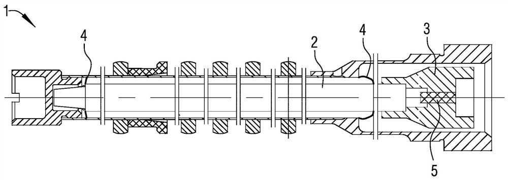
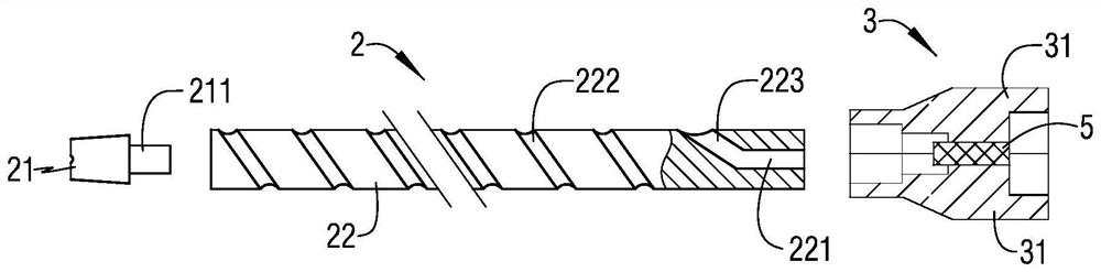
[0032] figure 1 It is a schematic diagram of the sectional structure principle of a thin-walled blind-hole slender shaft part used in an aero-engine; figure 2 It is a schematic diagram of the working state of a device for processing thin-walled blind holes and elongated shafts according to a specific embodiment of the present invention; image 3 for figure 2 Schematic diagram of the partially sectional structural principle of the decomposed state of the positioning rod and the sleeve member; Figure 4 for figure 2 Schematic diagram of the cross-sectional structure of the airbag body; Figure 5 for image 3 Schematic diagram of the three-dimensional structure prin...


PUM

PropertyMeasurementUnit
Wall thicknessaaaaaaaaaa
Diameteraaaaaaaaaa
Wall thicknessaaaaaaaaaa

Abstract

The invention provides a device for machining a thin-wall blind hole slender shaft. The device comprises a positioning rod, a sleeve part and an airbag body. The positioning rod comprises a positioning head and a rod body portion detachably connected with the positioning head. The airbag body is in a sleeve shape, an annular bottom face pasted to the first end face of the rod body portion is arranged at one end of the airbag body, and the sleeve part comprises two symmetric semicircular assemblies. According to the device for machining the thin-wall blind hole slender shaft, the part is effectively supported through an inflatable structure, thus, the overall rigidity of the part is enhanced, and the production efficiency is greatly improved.

Description

technical field [0001] The invention relates to the technical field of mechanical processing, in particular to a device for controlling deformation when processing the outer circular surface of a shaft body of a thin-walled hollow slender shaft part whose inner cavity is a blind hole. Background technique [0002] With the advancement of material science and processing technology, in order to reduce the weight under the premise of ensuring the rigidity and strength, the wall thickness of the shaft parts of the aero-engine is getting thinner and thinner. figure 1 It is a schematic diagram of the sectional structure principle of a thin-walled blind hole slender shaft part used in an aero-engine, see figure 1 As shown, the thin-walled blind hole slender shaft part 1 includes a shaft body 11 with a wall thickness of 0.5mm, and five annular bosses 12 are welded on the shaft body 11, and the two ends of the shaft body 11 are respectively A first end piece 13 and a second end piec...

Claims


Application Information

Patent Timeline
IPC IPC(8): B24B5/36B24B41/06
CPCB24B5/36B24B41/067
Inventor 鲁攀胡俊华陈超群姚俊征
Owner CHINA HANGFA SOUTH IND CO LTD
Why Eureka
Try Eureka