
Clamping jaw with correction function for yoke machining

A kind of jaw and function technology, applied in the direction of manufacturing tools, metal processing equipment, metal processing machinery parts, etc., can solve the problems of fine adjustment of movable jaws, insufficient lubrication, loosening, etc., to prevent clamping loosening, prolong service life, strengthen The effect of overall rigidity

Pending Publication Date: 2022-06-07
重庆明达天晨汽车零部件制造有限公司
View PDF8 Cites 0 Cited by
  • Summary
  • Abstract
  • Description
  • Claims
  • Application Information

AI Technical Summary

Problems solved by technology

[0003] After the clamping jaws on the market are clamped, they cannot be automatically locked. During use, they will become loose, and the position of each group of movable jaws cannot be fine-tuned, resulting in the inability to correct the position of the product and the inability to hold multiple clamps. For products made of different materials, if the hardness of the product material is poor, it will cause pinch damage. When clamping thin-walled products, it is easy to cause deformation and damage. Long-term mechanical movement will cause serious wear and tear due to insufficient lubrication.

Method used


Image

  • Clamping jaw with correction function for yoke machining
  • Clamping jaw with correction function for yoke machining
  • Clamping jaw with correction function for yoke machining

Examples


Embodiment Construction

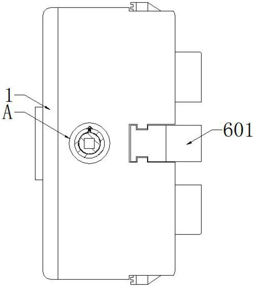
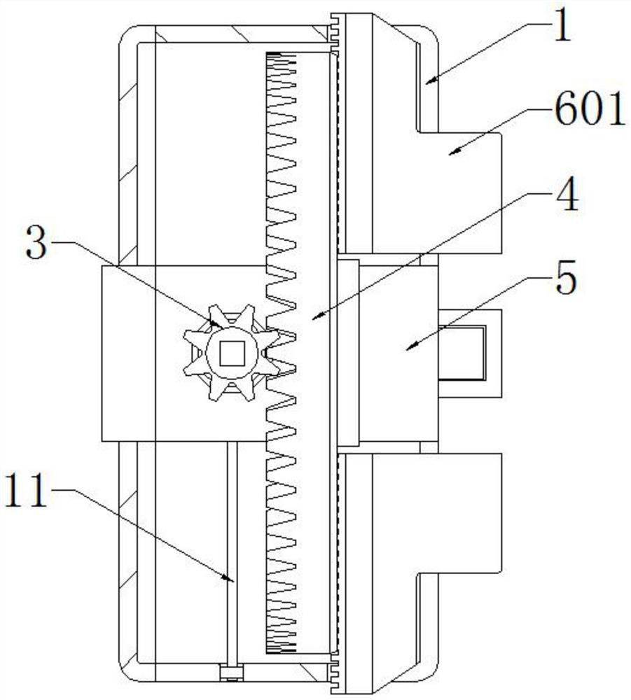
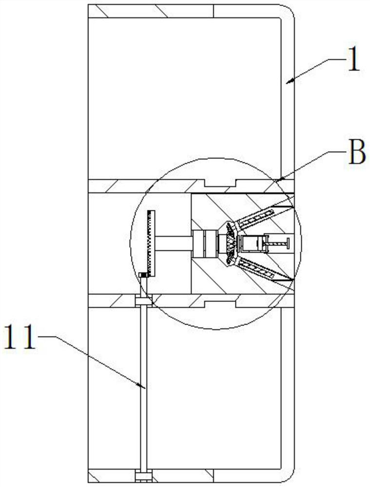
[0029] see figure 1 and Figure 4 , the present invention provides a technical solution: a clamping jaw with a correction function for yoke processing, comprising a chuck body 1 and a jaw assembly 6, the outer front end of the chuck body 1 is fixed with a self-locking assembly 2, and The self-locking assembly 2 includes a lock sleeve 201 , a rod sleeve 202 , a spring 203 and a boss pin 204 , the rod sleeve 202 is fixed inside the lock sleeve 201 , the spring 203 is arranged on the outside of the rod sleeve 202 , and the inner wall of the rod sleeve 202 is installed with The bump pin 204 and the rod sleeve 202 are elastically connected with the bump pin 204 through the spring 203, and the lower surface of the bump pin 204 is in close contact with the upper surface of the pinion bevel gear 3, and the center of the pinion bevel gear 3 and the lock sleeve 201 The centers of the circles coincide, the inner wall of the self-locking assembly 2 is provided with a small bevel gear 3, ...


PUM


Abstract

The invention discloses a clamping jaw with a correction function for yoke machining, and relates to the technical field of yoke machining, the clamping jaw comprises a chuck body and a jaw assembly, a self-locking assembly is fixed to the front end of the outer portion of the chuck body, and the self-locking assembly comprises a lock sleeve, a rod sleeve, a spring and a protruding block pin. When the small bevel gear rotates clockwise, the convex block pin rebounds, the small bevel gear is not limited by the convex block pin, the small bevel gear can normally rotate clockwise, when the small bevel gear rotates anticlockwise, the convex block pin does not rebounds, rotation of the small bevel gear is limited, clockwise rotation of the small bevel gear is clamping, and the small bevel gear is not limited by the convex block pin. The small bevel gear rotates anticlockwise for loosening, the convex block pin is responsible for preventing the small bevel gear from rotating anticlockwise after clamping, and the locking effect is achieved, when the small bevel gear is loosened, the convex block pin is pulled up to be separated from the groove of the small bevel gear, the convex block pin is rotated, the brim part of the convex block pin is lapped outside the lock sleeve, the small bevel gear can be normally rotated anticlockwise, and the locking effect is achieved. Therefore, the clamping jaw is provided with a locking structure.

Description

technical field [0001] The invention relates to the technical field of yoke processing, in particular to a clamping jaw with a correction function for yoke processing. Background technique [0002] The yoke is a machine that realizes variable-angle power transmission, and is used in the position where the direction of the transmission axis needs to be changed. It is the "joint" part of the universal transmission device of the automobile drive system. The yoke needs to use clamping jaws during processing. A machine tool accessory that clamps and positions the workpiece by the radial movement of the four movable jaws evenly distributed on the chuck body. The clamping jaws are composed of the chuck body, the movable jaws and the jaw drive mechanism. [0003] After the clamping jaws on the market are clamped, they cannot be automatically locked. During use, it will cause loosening, and it is impossible to fine-tune the position of each set of movable jaws, resulting in the inabi...

Claims


Application Information

Patent Timeline
IPC IPC(8): B23B31/10B23Q11/12
CPCB23B31/10B23Q11/12B23Q11/122Y02P70/10
Inventor 李宣明
Owner 重庆明达天晨汽车零部件制造有限公司
Learn More