Positive-pressure ash cooling system for biomass fluidized bed gasification furnace

A fluidized bed gasifier, biomass technology, applied in gasification process, granular/powder fuel gasification, chemical industry, etc., can solve the problem of not being able to discharge directly, prevent gas leakage and prevent deflagration accidents Effect

Inactive Publication Date: 2020-11-27
HARBIN BOILER
View PDF7 Cites 0 Cited by
  • Summary
  • Abstract
  • Description
  • Claims
  • Application Information

AI Technical Summary

Problems solved by technology

[0004] The purpose of the present invention is to solve the problem that the existing biomass gasification furnace cannot be discharged directly due to the extremely high content of fine ash in the gas produced by gasification, and the temperature of the fine ash separated by the fine ash separator is as high as 800°C, and further provides A positive pressure cold ash system for biomass fluidized bed gasifier

Method used


Image

  • Positive-pressure ash cooling system for biomass fluidized bed gasification furnace

Examples


specific Embodiment approach 1

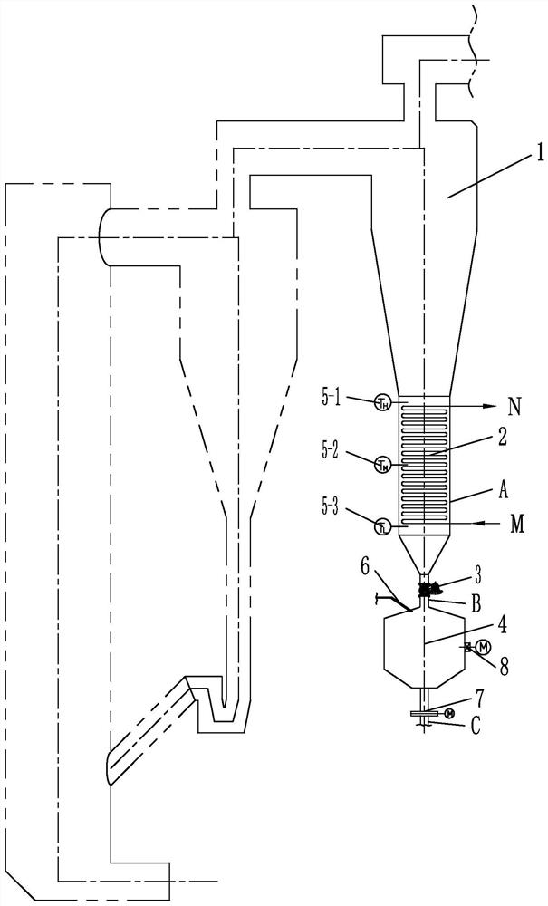
[0015] Specific implementation mode one: combine figure 1 Describe this embodiment, a positive pressure cold ash system for a biomass fluidized bed gasifier in this embodiment, which includes a fine ash separator 1, a cooling water heat exchanger 2, a rotary sealing valve 3, and an ash buffer The tank 4 and the electric gate 7, the standpipe A is arranged under the fine ash separator 1, the cooling water heat exchanger 2 is arranged in the standpipe A of the fine ash separator 1, and the ash buffer tank 4 is arranged in the fine ash separator 1, the ash buffer tank 4 is connected to the standpipe A of the fine ash separator 1 through the connecting pipe B, and the connecting pipe B between the ash buffer tank 4 and the fine ash separator 1 is provided with a rotary sealing valve 3, and the ash The ash discharge port below the buffer tank 4 is provided with an ash discharge pipe C, and the ash discharge pipe C is provided with an electric flashboard door 7 .

specific Embodiment approach 2

[0016] Specific implementation mode two: combination figure 1 Describe this embodiment, this embodiment also includes a material level gauge, the material level gauge is arranged on the inner wall of the riser A below the fine ash separator 1 . With such arrangement, the amount of ash in the vertical pipe A of the fine ash separator 1 is fed back through the temperature signal of the material level gauge. Other compositions and connections are the same as in the first embodiment.

specific Embodiment approach 3

[0017] Specific implementation mode three: combination figure 1 Describe this embodiment, the material level meter of this embodiment comprises high material level meter 5-1, middle material level meter 5-2 and low material level meter 5-3, high material level meter 5-1, middle material level meter 5 -2 and the low material level meter 5-3 are sequentially arranged on the inner wall of the vertical pipe A below the fine ash separator 1 from top to bottom. So set, the high material level gauge 5-1, the middle material level gauge 5-2 and the low material level gauge 5-3 are used to measure the amount of ash in different positions of the riser A of the fine ash separator 1. Other compositions and connections are the same as those in Embodiment 1 or Embodiment 2.

[0018] Specific implementation mode four: combination figure 1 Describe this embodiment, the cooling water heat exchanger 2 of this embodiment is a serpentine tube heat exchanger, the cooling water of the serpentine ...


PUM


Abstract

A positive-pressure ash cooling system for a biomass fluidized bed gasification furnace relates to the field of biomass fluidized bed gasification furnaces. According to the invention, the problem that the fine ash separated by the fine ash separator cannot be directly discharged because the content of the fine ash in the gasified gas of the existing biomass gasification furnace is extremely highand the temperature of the fine ash separated by the fine ash separator is up to 800 DEG C is solved. A vertical pipe is arranged below a fine ash separator; a cooling water heat exchanger is arrangedin the vertical pipe of the fine ash separator; an ash buffer tank is arranged below the fine ash separator, the ash buffer tank is connected with the vertical pipe of the fine ash separator througha connecting pipeline, a rotary sealing valve is arranged on a connecting pipeline between the ash buffer tank and the fine ash separator, an ash discharge pipeline is arranged at an ash discharge port below the ash buffer tank, and an electric flashboard door is arranged on the ash discharge pipeline. The system is used for recovering sensible heat of fine ash, and positive-pressure cold ash is safely discharged.

Description

technical field [0001] The invention relates to the field of biomass fluidized bed gasifiers, in particular to a positive pressure cold ash system for biomass fluidized bed gasifiers. Background technique [0002] The gas produced by biomass gasification has a high calorific value and can be developed and utilized as high-quality energy after purification treatment to meet the quality requirements of industrial production and domestic gas. The biomass gasifier is the main equipment of the gasification device. The content of fine ash in the gas is extremely high. In order to prevent the heat exchange from being contaminated by the heating surface at the tail of the gasifier, it is necessary to adopt fine ash separation measures, and the temperature of the fine ash separated by the fine ash separator is as high as 800°C, which cannot be discharged directly. The invention can recover the sensible heat of the fine ash and achieve the purpose of positive pressure cold ash dischar...

Claims


Application Information

Patent Timeline
IPC IPC(8): C10J3/56C10J3/72F28D1/047
CPCC10J3/56C10J3/72F28D1/0477C10J2300/0916Y02P20/10
Inventor 孙向文赵翠晶马玉喜王君峰姜孝国
Owner HARBIN BOILER
Why Eureka
Try Eureka