Supercharge Your Innovation With Domain-Expert AI Agents!

A prefabricated concrete wall component for building construction

A prefabricated wall and prefabricated technology, which is applied in the direction of building components, building structures, construction, etc., can solve the problems of grouting cavity voids, corrosion, waste of time and manpower, etc., to achieve tight filling and tamping, good safety performance, Facilitate the effect of assembly

Active Publication Date: 2021-08-31
陕西建工装配式智造科技有限公司
View PDF0 Cites 1 Cited by
  • Summary
  • Abstract
  • Description
  • Claims
  • Application Information

AI Technical Summary

Problems solved by technology

[0003] 1. The prefabricated wall is not immediately applied to the building after the production is completed, and the protruding steel bars need to be reserved during the production of the prefabricated wall. This part of the steel bars is always exposed outside. On the one hand, it will be affected by the environment. Oxidation or corrosion of the steel bars. On the other hand, the reserved steel bars are easy to collide with other places and things during transportation, causing the steel bars to bend. It is impossible to align the steel bar holes during assembly, and it takes effort to correct them, wasting time and manpower;
[0004] 2. When the assembly is completed, it is necessary to inject concrete into the grouting cavity in the prefabricated wall to fix the connection between the wall and the wall and the floor. However, the existing method uses grouting from the bottom. When the grout comes out from the top, it means that the grouting is complete. Although this method can complete the function of fixed connection, the concrete slurry contains many solid particles such as stones and sand, so there will be gaps in the grouting cavity, which reduces the strength of the prefabricated building and easily causes subsequent construction risks. Or the seismic strength does not meet the requirements, even endangering personal safety

Method used


Image

  • A prefabricated concrete wall component for building construction
  • A prefabricated concrete wall component for building construction
  • A prefabricated concrete wall component for building construction

Examples


Embodiment Construction

[0026] The following will clearly and completely describe the technical solutions in the embodiments of the present invention with reference to the accompanying drawings in the embodiments of the present invention. Obviously, the described embodiments are only some, not all, embodiments of the present invention. Based on the embodiments of the present invention, all other embodiments obtained by persons of ordinary skill in the art without making creative efforts belong to the protection scope of the present invention.

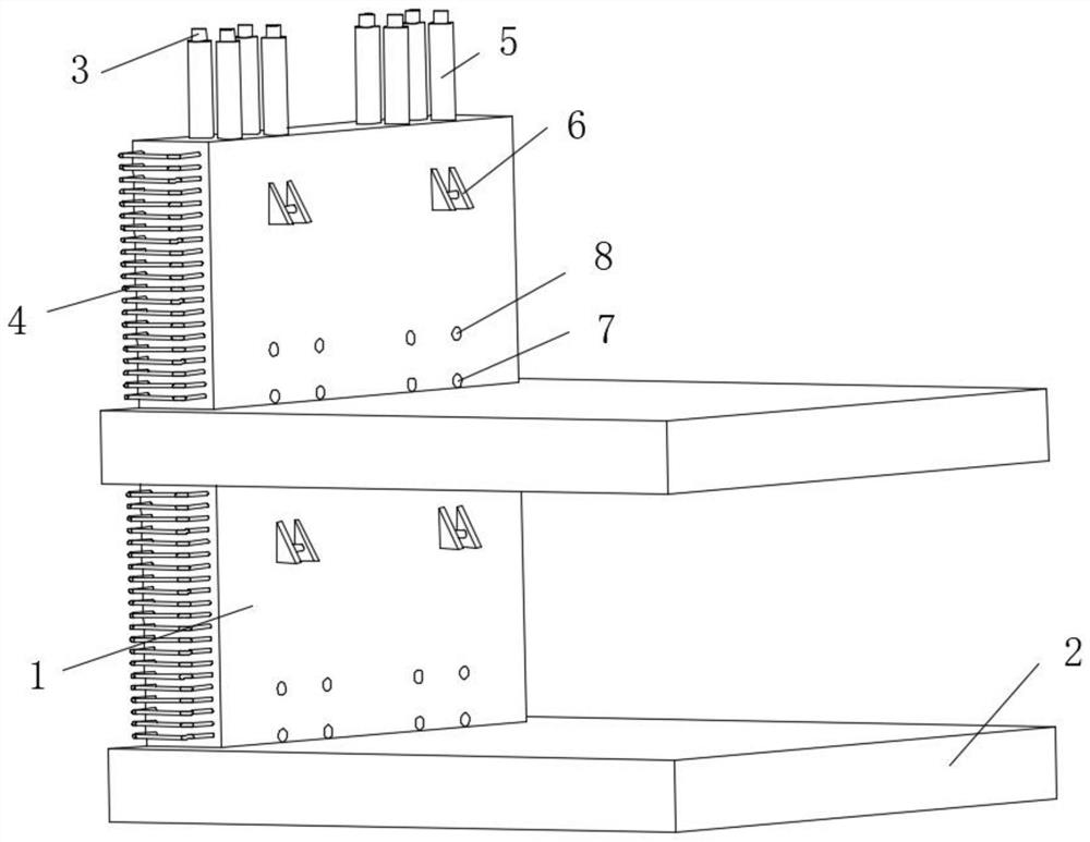
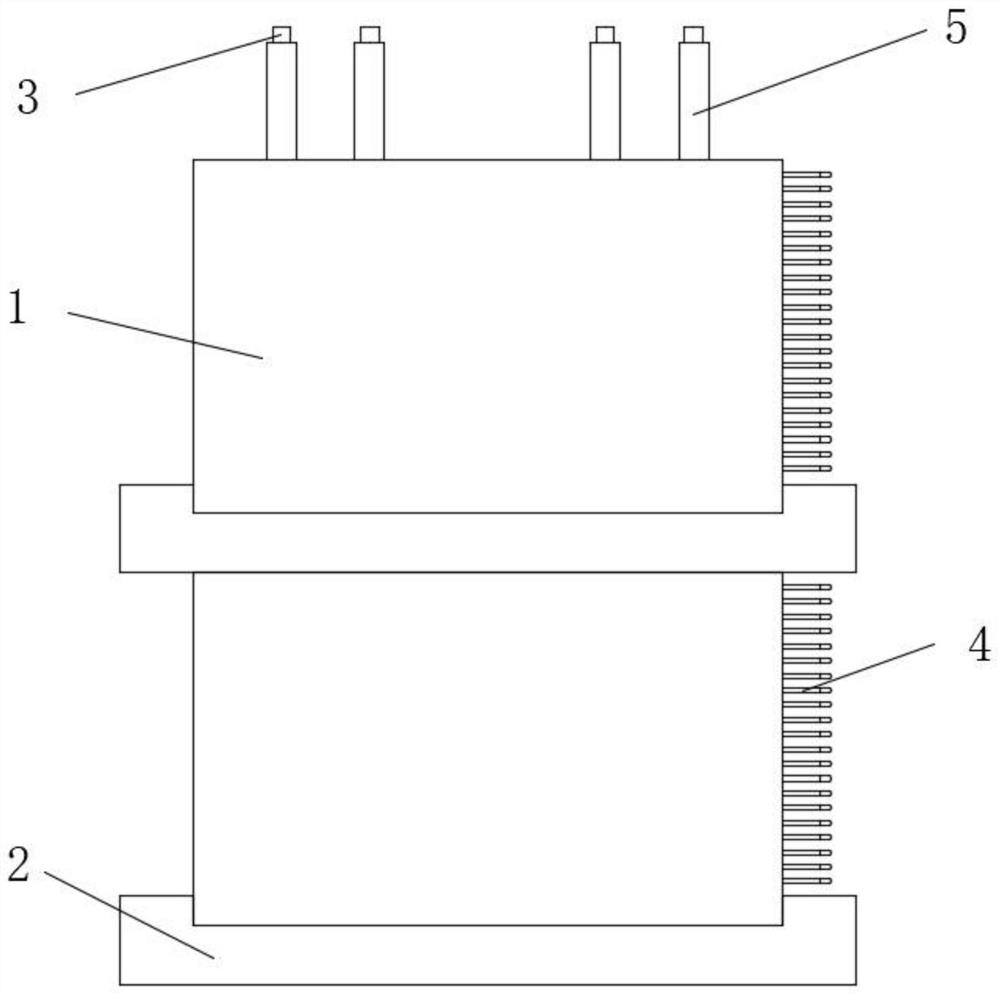
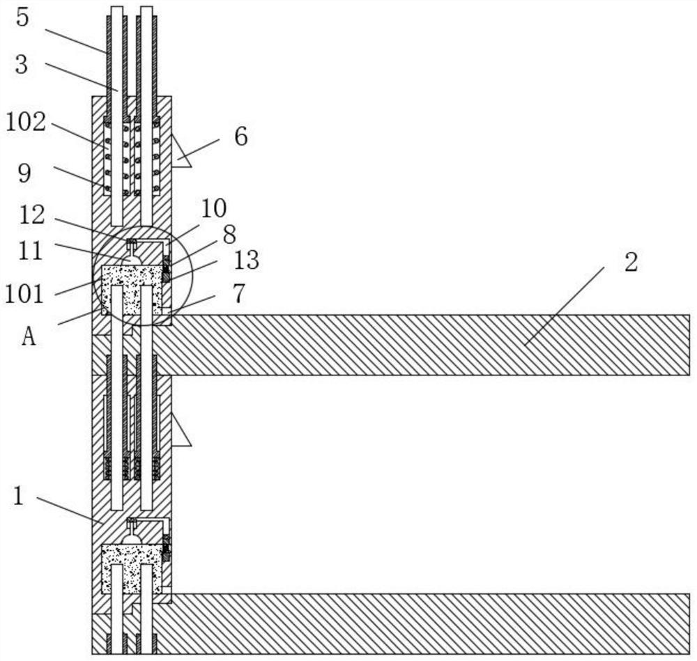
[0027] see Figure 1-8 , a prefabricated concrete wall component for building construction, including a prefabricated wall 1 and a prefabricated floor 2, the prefabricated wall 1 is fixed with a reserved steel bar 3 inside, and the reserved steel bar 3 runs through the top of the prefabricated wall 1 and protrudes , one side of the prefabricated wall 1 is fixedly installed with a connecting steel bar 4, the top of the front of the prefabricated wall 1 is fixed...


PUM


Abstract

The invention relates to the technical field of building construction, and discloses a prefabricated concrete wall component for building construction, including a prefabricated wall and a prefabricated floor, a grouting cavity is opened at the bottom of the prefabricated wall, and the prefabricated wall The grouting hole and the grouting hole are successively provided with the grouting hole and the grouting hole along the vertical direction from the top to the bottom, the grouting hole communicates with the bottom of the grouting cavity front, and the grouting hole communicates with the top of the grouting cavity front, so The top of the prefabricated wall is provided with a shrinkage groove, the outer ring of the reserved steel bar is movably connected with an anti-bending protective sleeve, and the interior of the prefabricated wall is provided with a mountain-shaped tunnel at the top of the grouting cavity. Three sliding holes are evenly opened inside the wall on the side of the grouting cavity. The end of the sliding hole away from the grouting cavity communicates with the end of the mountain-shaped channel. Fixed head, the prefabricated component has high quality, is easy to assemble, and has high strength.

Description

technical field [0001] The invention relates to the technical field of building construction, in particular to an assembled concrete prefabricated wall component for building construction. Background technique [0002] Nowadays, in order to quickly complete the construction of buildings, prefabricated buildings are often used. The commonly used ones are prefabricated concrete buildings, that is, prefabricated components are used to assemble the basic outline, and then the concrete building is reinforced. This construction method greatly reduces construction. time, and can also avoid the high frequency of construction site accidents, but there are still some problems in the existing prefabricated concrete building components: [0003] 1. The prefabricated wall is not immediately applied to the building after the production is completed, and the protruding steel bars need to be reserved during the production of the prefabricated wall. This part of the steel bars is always expo...

Claims


Application Information

Patent Timeline
Patent Type & Authority Patents(China)
IPC IPC(8): E04B2/00E04B2/74E04B2/82
CPCE04B2/00E04B2/74E04B2/82
Inventor 吕志君
Owner 陕西建工装配式智造科技有限公司
Features
  • R&D
  • Intellectual Property
  • Life Sciences
  • Materials
  • Tech Scout
  • Unparalleled Data Quality
  • Higher Quality Content
  • 60% Fewer Hallucinations
Learn More