A scanning trajectory planning method for a photographic three-dimensional scanner

A scanning trajectory and scanner technology, applied in the field of 3D scanning, can solve the problems of lack of scanning trajectory planning methods for photographic 3D scanners, inability to support automatic operation of equipment, and low acquisition efficiency

Active Publication Date: 2021-04-27
CHENGDU AIRCRAFT INDUSTRY GROUP
View PDF13 Cites 0 Cited by
  • Summary
  • Abstract
  • Description
  • Claims
  • Application Information

AI Technical Summary

Problems solved by technology

[0006] Therefore, relying on manual mode, whether it is repeated adjustments, gradually reducing the distance between adjacent photos, or directly collecting photos at a small distance, will lead to low collection efficiency
Integrating a photographic 3D scanner into automated equipment such as five-axis machine tools or robotic arms can solve the limitations caused by manual measurement. However, there is currently a lack of scanning trajectory planning methods for photographic 3D scanners installed on automated equipment, which cannot support the equipment. automatic running

Method used


Image

  • A scanning trajectory planning method for a photographic three-dimensional scanner
  • A scanning trajectory planning method for a photographic three-dimensional scanner
  • A scanning trajectory planning method for a photographic three-dimensional scanner

Examples


Embodiment 1

[0051] A scanning trajectory planning method for a photographic three-dimensional scanner, mainly comprising the following steps:

[0052] Step S1: Calibrate the actual single-frame effective range 1.8;

[0053] Step S2: solving the flattest envelope direction 2.4 of the surface to be measured 2.1;

[0054] Step S3: solving the initial guiding line 3.1 and the primary guiding line 3.2;

[0055] Step S4: Solve the initial node 4.1 and the measurement direction at the initial node 4.1;

[0056] Step S5: splicing inspection and correction of the adjacent initial node 4.1 on the initial guiding line 3.1;

[0057] Step S6: solving the secondary guiding line 6.1, the secondary node 6.2 and their measurement directions;

[0058] Step S7: Splicing inspection and correction of adjacent secondary nodes 6.2 on each secondary guiding line 6.1;

[0059] Step S8: Splicing inspection and correction of adjacent secondary nodes 6.2 on each primary guiding line 3.2;

[0060] Step S9: Inver...

Embodiment 2

[0065] A scanning trajectory planning method for a photographic three-dimensional scanner, mainly comprising the following steps:

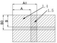
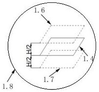
[0066] Step S1: if Figure 1-3 As shown, calibrate the actual single effective range of 1.8; respectively adjust the distance between the two photos along the length A0 and width B0 directions of the single photo range 1.1 of the photographic 3D scanner, and observe whether the two photos can be spliced , the maximum distance that can be spliced ​​in the direction of length A0 and width B0 of a single photo range of 1.1 is length A and width B, the depth of field of the 3D scanner is the height H, and the focal point of the 3D scanner is the center of symmetry, the range of the cuboid is obtained as The actual single-frame effective range of the calibrated 3D scanner is 1.8;

[0067] Step S2: if Figure 4 As shown, solve the flattest envelope direction 2.4 of the surface to be tested 2.1, and solve two planes that are parallel to each other and ...

Embodiment 3

[0088] A scanning trajectory planning method for a photographic three-dimensional scanner, mainly comprising the following steps:

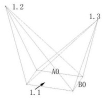
[0089] Such as Figure 1-3 As shown, the photographic 3D scanner can solve the spatial point cloud of a curved surface within a certain range through at least two cameras, that is, the first camera 1.2 and the second camera 1.3, and this range is a single photo of the photographic 3D scanner Range 1.1 (length*width*height=A0*B0*H). The range 1.1 of a single photo of a photographic 3D scanner is generally smaller than the size of the surface to be measured 2.1 of the part, so multiple single images are required for splicing, and the range 1.1 between two adjacent single photos taken by multiple frames must be If there is a minimum splicing intersection area of ​​1.5, then the range of a single photo minus 1.1 is the effective range of a single frame at the actual focal plane of 1.4; if the depth of field of the camera is set to H, then the upper a...


PUM


Abstract

The invention discloses a scanning trajectory planning method of a photographic three-dimensional scanner. The invention plans the scanning trajectory of the photographic three-dimensional scanner according to the digital model of parts, which not only reduces the dependence on the experience of workers, but also improves the collection efficiency; at the same time, the present invention The trajectory planned by the invention can also be used as a photographic three-dimensional scanner for integrated application on automatic equipment such as five-axis machine tools, thereby realizing the supporting conditions for automatic measurement. The invention optimizes the connection of all nodes and connects them in this order, which can not only ensure that the photos taken at each node can be spliced ​​with the collected photos to avoid splicing failure, but also ensure the shortest moving path and improve efficiency.

Description

technical field [0001] The invention belongs to the technical field of three-dimensional scanning, and in particular relates to a scanning trajectory planning method of a photographic three-dimensional scanner. Background technique [0002] With the development of modern industrial manufacturing level, a large number of product parts use irregular and complex surfaces, and its design, production, testing and other links need to carry out a large number of 3D surface entity digitization and 3D scanning, and there is an urgent need for fast and efficient 3D scanning technology. The camera-type 3D scanner can solve the scanning local point cloud through multi-angle, multi-camera heterodyne multi-frequency phase shift and other technical processing; through multiple shooting, multiple photos overlap local texture or surface marker recognition , to realize the splicing of multiple local point clouds, and then realize the digital collection of the entire surface information of lar...

Claims


Application Information

Patent Timeline
Patent Type & Authority Patents(China)
IPC IPC(8): G01B11/245
CPCG01B11/245
Inventor 易晓满黄明聪张西成张桂秦枭品唐李
Owner CHENGDU AIRCRAFT INDUSTRY GROUP
Why Eureka
Try Eureka