Magnetic induction type current calculation method suitable for parallel three-phase line fault line selection

A technology for fault line selection and current calculation, which is applied in the direction of only measuring current, fault location, and measuring current/voltage. The complexity, the simplification of the calculation process and steps, the effect of improving the measurement accuracy

Active Publication Date: 2020-11-27
YUNNAN POWER GRID CO LTD LINCANG POWER SUPPLY BUREAU
View PDF14 Cites 6 Cited by
  • Summary
  • Abstract
  • Description
  • Claims
  • Application Information

AI Technical Summary

Problems solved by technology

[0011] The purpose of the present invention is to provide a magnetic induction current calculation method suitable for fault line selection of parallel three-phase lines, to solve the problems that the power-off installation is too complicated, the existing measurement method cannot measure three phases at the same time, and the existing calculation met

Method used


Image

  • Magnetic induction type current calculation method suitable for parallel three-phase line fault line selection
  • Magnetic induction type current calculation method suitable for parallel three-phase line fault line selection
  • Magnetic induction type current calculation method suitable for parallel three-phase line fault line selection

Examples


Embodiment Construction

[0042] In order to make the object, technical solution and advantages of the present invention clearer, the invention will be further described in detail below in conjunction with the accompanying drawings and embodiments. It should be understood that the specific embodiments described here are only used to explain the present invention, not to limit the present invention.

[0043] figure 1 The assembly method of the magnetic sensor is shown: parallel three-phase wire wire I, wire II, wire III and the distance between the centers of adjacent wires is L, and the magnetic field sensor is arranged in a circular direction at a distance r from the center of the wire. The magnetic field sensor adopts a TMR sensor. The magnetic field sensor is a magnetic field strength sensor with a single-dimensional sensitive direction.

[0044] figure 1 From left to right in the middle are wire Ⅰ, wire Ⅲ, and wire Ⅱ. The magnetic field sensor is equipped with 4 magnetic field sensors. The sensit...


PUM


Abstract

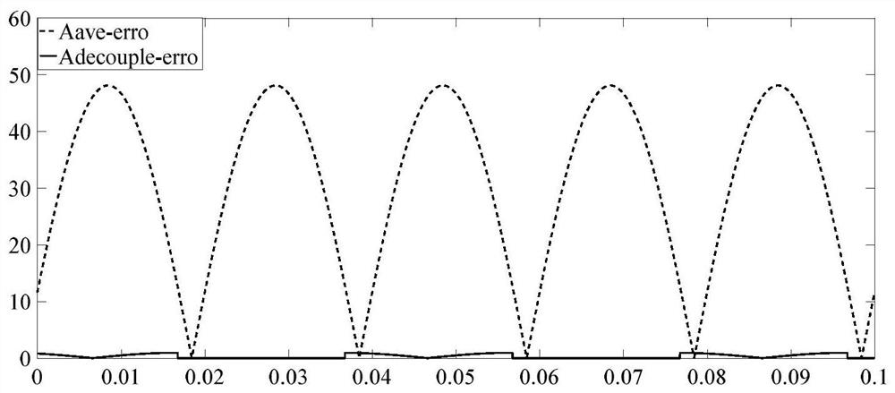
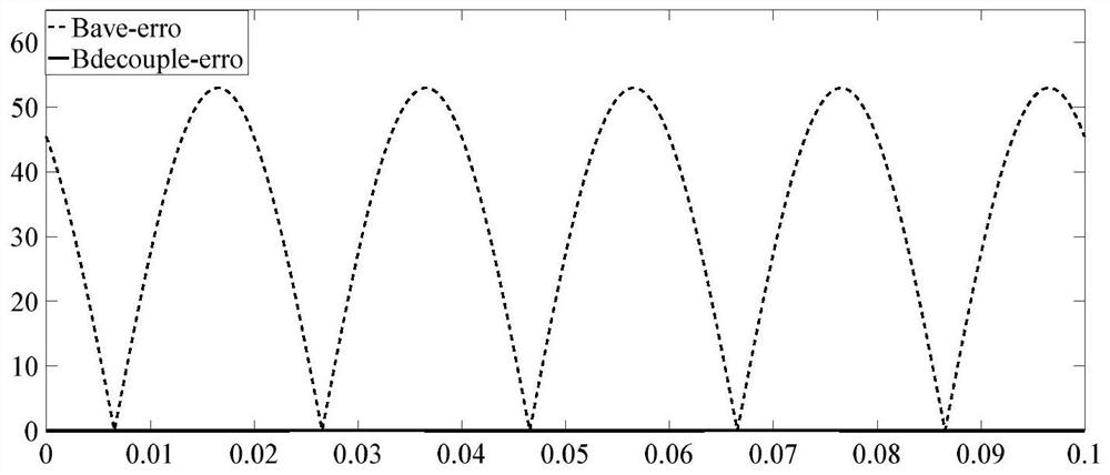
The invention discloses a magnetic induction type current measurement method suitable for parallel three-phase line fault line selection, and relates to the technical field of power grid fault measurement. Magnetic field sensors are annularly arranged at the position away from the center of a wire by the distance R, and the difference between the sensitive directions of the adjacent magnetic fieldsensors on the same wire is 90 degrees; and decoupling calculation is performed on the instantaneous current value of the three-phase wire through the measurement values of the magnetic field sensors, so that a three-phase current measurement value after decoupling compensation can be obtained. According to the method, when magnetic induction type current measurement is carried out on the parallel three-phase wires, measurement errors caused by mutual influence of magnetic fields generated by the parallel three-phase wires are reduced, so that more accurate measurement values are obtained inmeasurement scenes with higher requirements on measurement accuracy, such as small-current grounding fault line selection, and the success rate of line selection is increased. According to the algorithm, many complex quantities in compensation calculation are adaptively simplified, the calculation steps and complexity are reduced, and the requirement for the calculation capability of measurement equipment is reduced.

Description

technical field [0001] The invention relates to the technical field of grid fault measurement, in particular to a magnetic induction current calculation method suitable for fault line selection of parallel three-phase lines. Background technique [0002] Over the years, ground fault line selection and location has been a subject of research at home and abroad. More than 90% of the faults in the power system occur in the distribution network, and the single-phase ground fault accounts for more than 70%. Distribution lines have the characteristics of long power supply distance, complex structure, and many equipment components, and the components are easily damaged by weather and other factors during operation, and line grounding faults occur frequently, which has a great impact on power supply reliability. Domestic ground fault line selection is mainly realized by monitoring zero-sequence current and two-phase current. Under normal operating conditions, the three-phase curre...

Claims


Application Information

Patent Timeline
IPC IPC(8): G01R19/00G01R31/08
CPCG01R19/0092G01R31/088G01R31/086Y04S10/52
Inventor 郭平杨文呈黄继盛周源杨彦仙杨琦王存美孙超徐军华
Owner YUNNAN POWER GRID CO LTD LINCANG POWER SUPPLY BUREAU
Why Eureka
Try Eureka