Lens barrel, optical imaging lens and electronic device

An optical imaging lens and lens barrel technology, which is applied in the field of lens barrels, optical imaging lenses and electronic devices, and can solve problems such as difficulty in adjusting the shading sheet to an appropriate position.

Pending Publication Date: 2020-11-27
ZHEJIANG SUNNY OPTICAL CO LTD
View PDF0 Cites 0 Cited by
  • Summary
  • Abstract
  • Description
  • Claims
  • Application Information

AI Technical Summary

Problems solved by technology

[0007] The main purpose of the present invention is to provide a lens barrel, an optical imaging lens and an electronic device to solve the problem that the optical imaging lens in the prior art is difficult to adjust the shading sheet to an appropriate position

Method used


Image

  • Lens barrel, optical imaging lens and electronic device
  • Lens barrel, optical imaging lens and electronic device
  • Lens barrel, optical imaging lens and electronic device

Examples


Embodiment 1

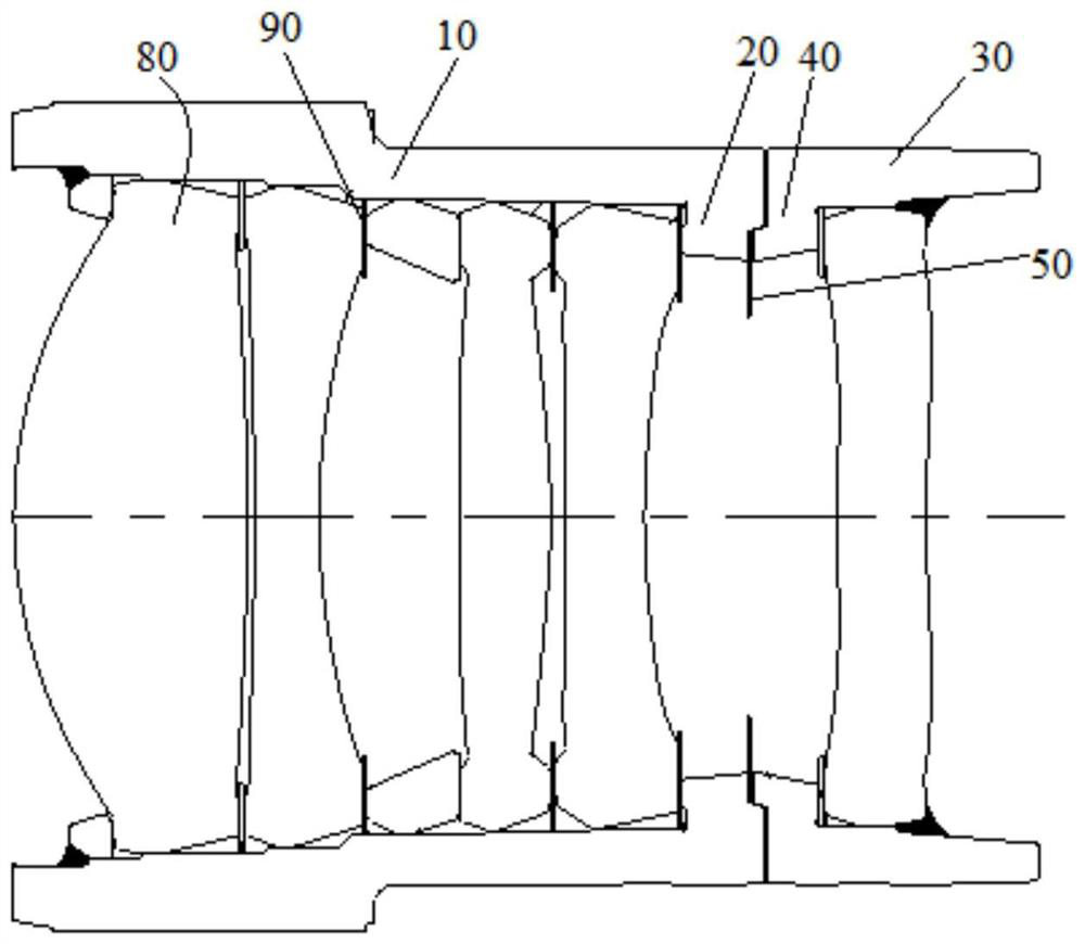
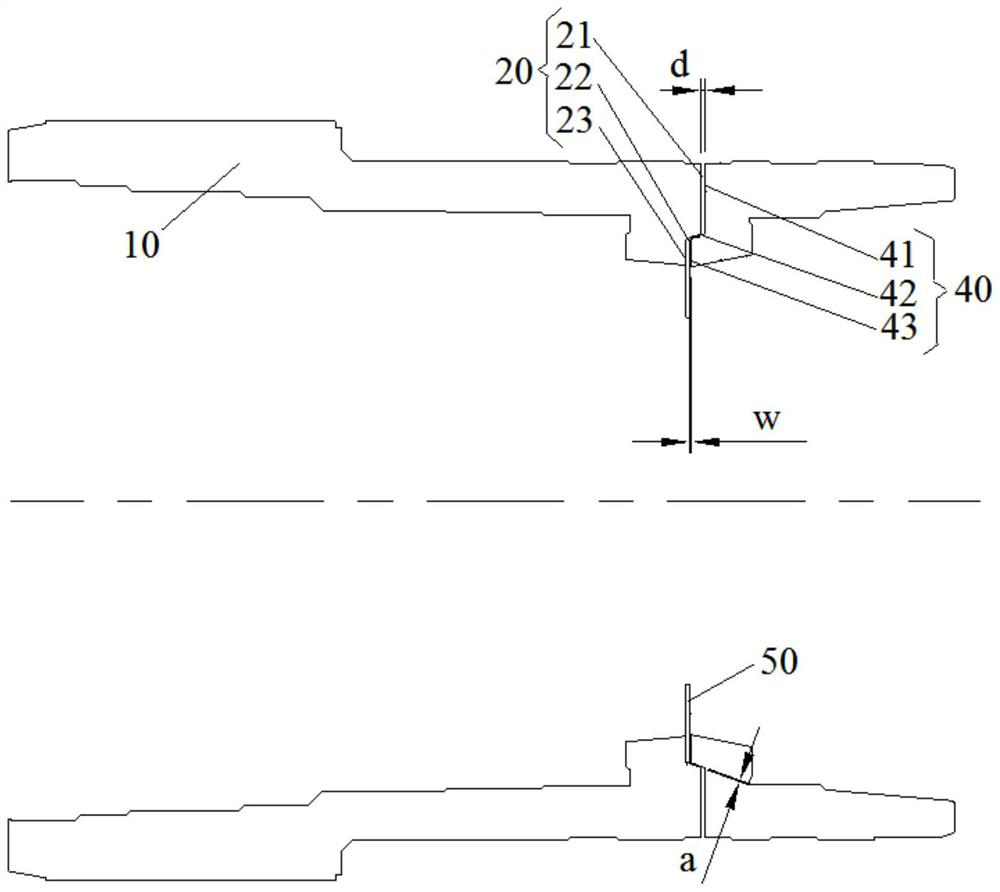
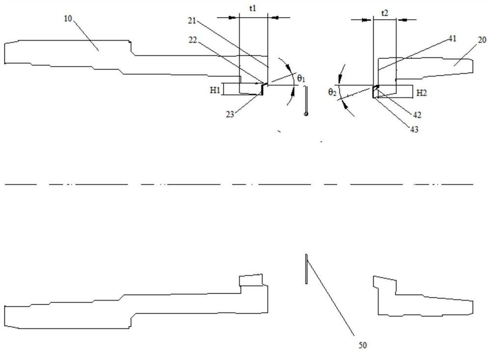
[0040] Such as figure 2 and image 3 As shown, the first connection structure 20 includes a first outer receiving surface 21, a first axial connection surface 22, and a first inner receiving surface 23 connected in sequence toward the direction close to the optical axis 60 of the lens barrel. The first inner receiving surface 23 is close to the image-side end of the first lens barrel 10 relative to the first outer receiving surface 21; the second connecting structure 40 includes a second outer receiving surface 41 and a second axial connecting surface connected in sequence toward the direction close to the optical axis 60 42 and the second inner receiving surface 43, the second outer receiving surface 41 is closer to the object-side end of the second lens barrel 30 relative to the second inner receiving surface 43; wherein, after the first connection structure 20 is connected to the second connection structure 40, The first axial connecting surface 22 and the second axial co...

Embodiment 2

[0053] The difference from the first embodiment is that the specific structure of the second connecting structure 40 is different.

[0054] Such as Figure 4 and Figure 5 As shown, at least a part of the first connection structure 20 is close to the optical axis 60 relative to the inner barrel wall of the lens barrel body of the first lens barrel 10 , and at least a part of the second connection structure 40 is relatively close to the lens barrel body of the second lens barrel 30 The inner wall of the cylinder is close to the optical axis 60 , the surface of the second connecting structure 40 away from the first connecting structure 20 has a supporting structure 70 , and the supporting structure 70 is supported by the lens 80 . The arrangement of the support structure 70 facilitates the support and fixation of the second connection structure 40 and the lens 80 , and facilitates the adjustment of the position between the lens 80 and the light shielding element 50 .

[0055] ...

Embodiment 3

[0059] The difference from the first embodiment is that the specific structure of the light shielding element 50 is different.

[0060] exist Figure 6 In the specific embodiment shown, the shading element 50 includes a substrate layer 51, a first surface layer 52 and a second surface layer 53 positioned on both sides of the substrate layer 51, the substrate layer 51 can be made of plastic material, and the first surface layer 52 and the second surface layer 53 The second surface layer 53 is a black carbonaceous material layer. Setting the first surface layer 52 and the second surface layer 53 in black facilitates the absorption of light by the shading element 50 and reduces the generation of stray light.


PUM

PropertyMeasurementUnit
Lengthaaaaaaaaaa

Abstract

The invention provides a lens barrel, an optical imaging lens and an electronic device. The lens barrel includes: a first lens barrel having a first connection structure at an object-side end thereof;a second lens barrel having a second connecting structure matched with the first connecting structure at an image-side end thereof; and an anti-dazzling screen arranged between the first connecting structure and the second connecting structure. The problem that in the prior art, it is difficult to adjust the anti-dazzling screen of the optical imaging lens to a proper cutting position is solved.

Description

technical field [0001] The invention relates to the technical field of optical equipment imaging, in particular to a lens barrel, an optical imaging lens and an electronic device. Background technique [0002] At present, in a general imaging lens set, except for lenses mainly used for imaging, annular optical elements are usually arranged between the lenses, so that there is an appropriate optical distance between the lenses. When other optical elements such as shading sheets are required, the shading sheets can only be placed between the two sides of the annular optical element and the adjacent lenses, so it is difficult to adjust the shading sheets to Corresponds to the appropriate position of the optical axis. [0003] Furthermore, the existing annular optical elements are usually manufactured by injection molding, and their surfaces are smooth and bright with high reflectivity, so they cannot effectively attenuate the reflected light intensity of stray light incident o...

Claims


Application Information

Patent Timeline
IPC IPC(8): G02B7/00G02B7/02
CPCG02B7/00G02B7/021
Inventor 张变张芳戴付建赵烈烽
Owner ZHEJIANG SUNNY OPTICAL CO LTD
Why Eureka
Try Eureka