Automobile motor with long service life

A motor, long-life technology, applied in the direction of electric components, electrical components, electromechanical devices, etc., can solve the problems of shortening the service life of the motor, inconvenient disassembly of the motor, not meeting the needs of use, etc., to achieve easy separation and assembly, easy disassembly, The effect of improving usability

Inactive Publication Date: 2020-11-27
张红卫
View PDF0 Cites 0 Cited by
  • Summary
  • Abstract
  • Description
  • Claims
  • Application Information

AI Technical Summary

Problems solved by technology

[0006] Aiming at the above-mentioned shortcomings existing in the prior art, the present invention provides an automobile motor with a long service life, which can effectively overcome the long-term existence of the prior art and easily lead to damage to the wires, thereby affecting the operation of the motor and shortening the The service life of the motor increases the maintenance cost, and the motor is inconvenient to disassemble, and the maintenance and inspection are troublesome, which increases the difficulty of work, wastes time, reduces practicability, and does not meet the needs of modern people.

Method used


Image

  • Automobile motor with long service life
  • Automobile motor with long service life
  • Automobile motor with long service life

Examples


Embodiment 1

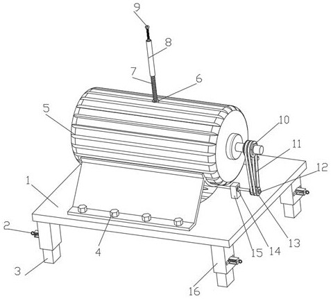
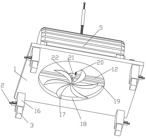
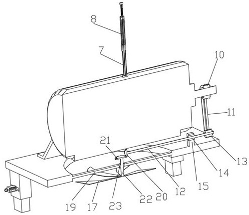
[0032] Such as Figure 1-5 An automotive motor with long service life is shown, including a base plate 1 and a motor 5. The bottom of the base plate 1 is symmetrically fixedly connected with a cover plate 16, and the inside of the cover plate 16 is connected with a support plate 3 through sliding holes, and the outer wall of the cover plate 16 A positioning structure 2 for positioning the support plate 3 is provided. A through hole 18 is provided on the top of the bottom plate 1. The inner wall of the through hole 18 is fixedly connected with a second support plate 19, and the second support plate 19 is connected with a second rotation rod 22. The second rotation The top of the rod 22 is fixedly connected with a driven bevel gear 21, the bottom of the second rotating rod 22 is uniformly fixedly connected with a fan blade 17 for driving air flow along the circumferential direction, and the output end of the motor 5 is fixedly connected with a driving pulley 10. Pulley 10 is mov...

Embodiment 2

[0034] Embodiment 2 is a further improvement to Embodiment 1.

[0035] Such as Figure 1-5A long-life automobile motor shown includes a base plate 1 and a motor 5. The bottom of the base plate 1 is symmetrically fixedly connected with a cover plate 16, and the cover plate 16 is connected with a support plate 3 through sliding holes, and the cover plate 16 is slidably connected. The outer wall is provided with a positioning structure 2 for the positioning of the support plate 3. The positioning structure 2 includes a pull ring 201, a U-shaped plate 202, a wedge block 203, a wedge-shaped groove 204, a slide bar 205, a first spring 206 and a chute 207, and the U-shaped plate 202 is fitted and slidably connected with a slide bar 205 through the slide hole, the outer end of the slide bar 205 is fixedly connected with a pull ring 201 for pulling the slide bar 205, and the inner end of the slide bar 205 is fixedly connected with a wedge-shaped block 203 with the hypotenuse facing dow...

Embodiment 3

[0037] Embodiment 3 is a further improvement to Embodiment 1.

[0038] Such as Figure 1-5 A long-life automobile motor shown includes a base plate 1 and a motor 5. The bottom of the base plate 1 is symmetrically fixedly connected with a cover plate 16, and the cover plate 16 is connected with a support plate 3 through sliding holes, and the cover plate 16 is slidably connected. The outer wall is provided with a positioning structure 2 for the positioning of the support plate 3, and the top of the bottom plate 1 is provided with a through hole 18, and the inner wall of the through hole 18 is fixedly connected with a second support plate 19, and the second support plate 19 is connected with a second rotating rod 22. The top of the rotating rod 22 is fixedly connected with the driven bevel gear 21, the bottom of the second rotating rod 22 is uniformly fixedly connected with the fan blade 17 for driving air flow along the circumferential direction, and the output end of the motor...


PUM


Abstract

The invention relates to the technical field of automobile motors, and particularly relates to an automobile motor with long service life. The automobile motor comprises a bottom plate, wherein the bottom plate is provided with a sleeve plate, the sleeve plate is provided with a supporting plate and a positioning structure, the bottom plate is provided with a through hole, a second supporting plate is arranged in the through hole, the second supporting plate is connected with a second rotating rod, the second rotating rod is provided with a driven bevel gear, the second rotating rod is provided with fan blades for driving air to flow, the motor is provided with a driving belt pulley, the driving belt pulley is provided with a belt, the belt is provided with a driven belt pulley, the drivenbelt pulley is provided with a first rotating rod, the first rotating rod is provided with a driving bevel gear, the driving bevel gear is connected with a driven bevel gear, the motor is provided with a transverse block, a cable is arranged on the transverse block, the transverse block is provided with a threaded pipe, the threaded pipe is provided with a threaded sleeve, the threaded sleeve isprovided with a cylinder, the cylinder is provided with a second spring, the second spring is provided with a connector, a top pipe of the cable penetrates through the threaded pipe, the threaded sleeve, the cylinder and the second spring to be fixedly connected with the connector. The connector can be conveniently adjusted to the contact height, the second spring facilitates connection directionof connector adjustment, and the use is facilitated.

Description

technical field [0001] The invention relates to the technical field of automobile electric motors, in particular to an automobile electric motor with long service life. Background technique [0002] With the development of society and the advancement of science and technology, people use electric motors more and more widely in the research process of the automotive field. There are many types of electric motors, such as booster motors, wiper motors, and sunroof motors. [0003] Automobile motor refers to an electromagnetic device that realizes the conversion or transmission of electric energy according to the law of electromagnetic induction. The motor is also called, and it is represented by the letter "M" in the circuit. Its main function is to generate driving torque as the power of electric vehicles. source, but the existing automotive motors are prone to vibration during work, causing friction between the wires and the car body, which will easily cause damage to the wir...

Claims


Application Information

Patent Timeline
Patent Type & Authority Applications(China)
IPC IPC(8): H02K7/116H02K9/06H02K5/26
CPCH02K5/26H02K7/116H02K9/06
Inventor 张红卫
Owner 张红卫
Why Eureka
Try Eureka