
Glass rod drilling equipment calibration device and clamp horizontal calibration method

A technology for drilling equipment and calibration devices, which is applied in the direction of measuring devices, mechanical devices, mechanical measuring devices, etc., can solve the problems of increasing inspection errors, reducing stability, and insufficient length of dial indicator brackets, etc., to achieve accurate measurement results, Guarantee the effect of measurement accuracy and stability

Pending Publication Date: 2020-12-01
WUHAN BRIGHTCORE OPTICAL FIBER CO LTD
View PDF0 Cites 0 Cited by
  • Summary
  • Abstract
  • Description
  • Claims
  • Application Information

AI Technical Summary

Problems solved by technology

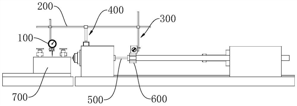
[0004] The machine tool has a guide sleeve and a support sleeve between the spindle and the fixture. The spindle of the machine tool cannot be calibrated close to the fixture due to the travel limit, and the conventional dial indicator bracket is not long enough to complete the measurement. However, simply increasing the dial indicator bracket length Will reduce stability and increase test error

Method used


Image

  • Glass rod drilling equipment calibration device and clamp horizontal calibration method
  • Glass rod drilling equipment calibration device and clamp horizontal calibration method
  • Glass rod drilling equipment calibration device and clamp horizontal calibration method

Examples


Embodiment Construction

[0034] In order to make the purpose, technical solutions and advantages of the embodiments of the present invention clearer, the technical solutions in the embodiments of the present invention will be clearly and completely described below in conjunction with the drawings in the embodiments of the present invention. Obviously, the described embodiments It is a part of embodiments of the present invention, but not all embodiments. Based on the embodiments of the present invention, all other embodiments obtained by persons of ordinary skill in the art without creative efforts fall within the protection scope of the present invention.

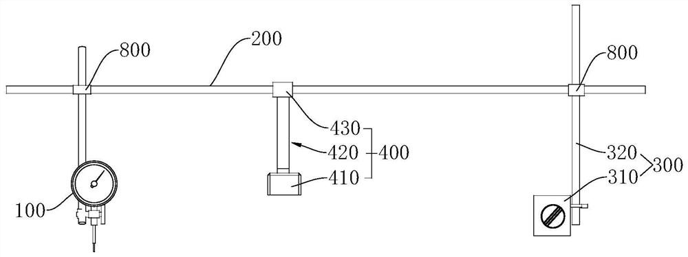
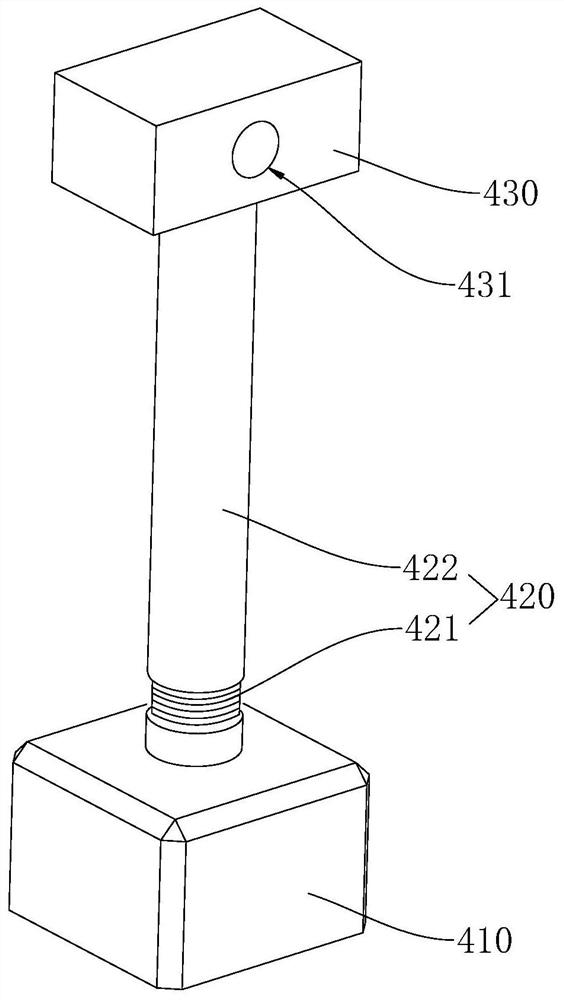
[0035] Combine below figure 1 and figure 2 A calibration device for glass rod drilling equipment according to an embodiment of the present invention is described. The calibration device for glass rod drilling equipment includes: a dial indicator 100 , an extension rod 200 , a magnetic support 300 and a movable support 400 .

[0036] The extensi...


PUM


Abstract

The invention relates to the technical field of glass rod processing equipment, and provides a glass rod drilling equipment calibration device and a clamp horizontal calibration method. The glass roddrilling equipment calibration device comprises a dial indicator, an extension bar, a magnetic support and a movable support; the extension bar is horizontally arranged, the magnetic support and the movable support are vertically arranged, and a probe of the dial indicator is downward. The extension bar is connected with the upper part of the dial indicator and the upper part of the magnetic support; the movable support is arranged between the dial indicator and the magnetic support; the upper portion of the movable support is in sliding connection with the extension rod; and the relative sliding direction of the upper portion of the movable support and the extension rod is in the axial direction of the extension rod. The calibration device of the glass rod drilling equipment is connectedwith the dial indicator through the extension bar, the supporting distance of the dial indicator can be increased, and the calibration requirement of the glass rod drilling equipment is met. The extension bar is supported by the magnetic support and the movable support at the same time, so that the stability of the extension bar can be guaranteed, and the measurement result is accurate.

Description

technical field [0001] The invention relates to the technical field of glass rod processing equipment, in particular to a calibration device for glass rod drilling equipment and a method for calibrating the level of a fixture. Background technique [0002] Now in the actual production process, the jig parts on the centering shaft jig of the glass rod drilling machine that are in contact with the product are made of ABS material. Because the deformation of ABS is relatively large after long-term use, it is necessary to regularly check the tooling jig Verify compliance with production standards. [0003] Calibration without a meter will cause the workpiece to be clamped not on the horizontal axis, and it will not be possible to find out whether the fixture is deformed in time. Use the method of extending the tool rod and feeler gauge to check the fixture. Since the longer the tool rod is extended, the stability will be worse, and the inspection error will be too large, so it ...

Claims


Application Information

Patent Timeline
IPC IPC(8): G01B5/00G01B5/02G01B5/24G01B5/30G01C9/24
CPCG01B5/0002G01B5/02G01B5/24G01B5/30G01C9/24
Inventor 梁应龙
Owner WUHAN BRIGHTCORE OPTICAL FIBER CO LTD
Learn More