Tumor tissue imaging device and method

A technology of tumor tissue and imaging device, which is applied in medical science, diagnosis by using light, sensors, etc., can solve the problem of low flexibility and achieve the effect of measuring a wide range of objects and improving flexibility and applicability

Active Publication Date: 2020-12-04
CHANGCHUN UNIV OF SCI & TECH
View PDF9 Cites 2 Cited by
  • Summary
  • Abstract
  • Description
  • Claims
  • Application Information

AI Technical Summary

Problems solved by technology

[0006] The purpose of the present invention is to provide a tumor tissue imaging device and method, aiming to solve the technical problem of the low flexibility of the "optical staining" tumor tissue imaging device in the prior art

Method used


Image

  • Tumor tissue imaging device and method
  • Tumor tissue imaging device and method
  • Tumor tissue imaging device and method

Examples


Embodiment 1

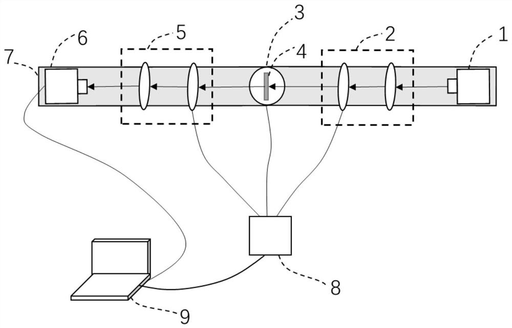
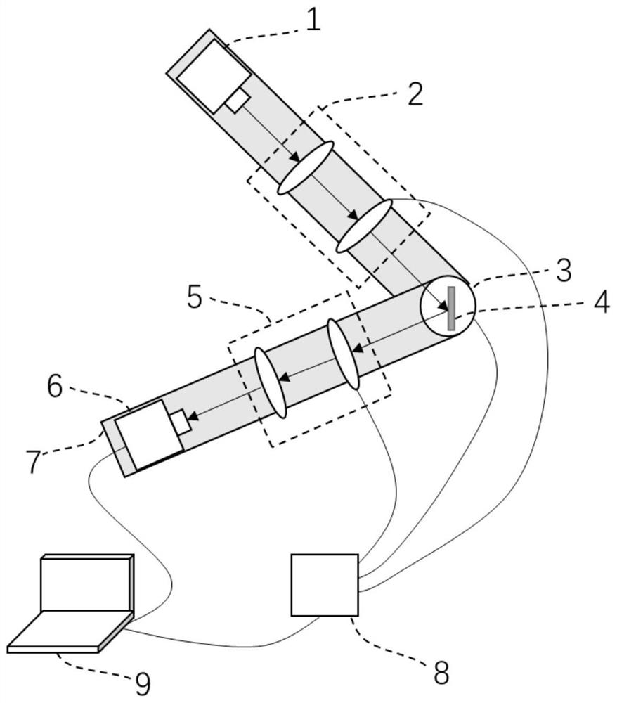
[0030] Figure 1-2 The imaging device for tumor tissue provided in this embodiment is shown. as attached figure 1 , 2 As shown, the tumor tissue imaging device provided in this embodiment includes a light source 1 , a polarizer 2 , a rotating wheel 3 , an analyzer 5 , and a camera 6 .

[0031] A light source 1 , a polarizer 2 , an analyzer 5 , and a camera 6 are distributed along the optical path, and the rotating wheel 3 is located between the polarizer 2 and the analyzer 5 .

[0032] The rotating wheel 3 is used to rotate the polarizer 2 or the analyzer 5 according to a preset angle to switch the imaging mode, and the imaging mode includes reflection imaging and transmission imaging.

[0033] figure 1 It is a schematic structural diagram of an imaging device for tumor tissue during transmission imaging shown in Embodiment 1, figure 2 It is a schematic structural diagram of an imaging device for tumor tissue during reflective imaging shown in Embodiment 1.

[0034] The...

Embodiment 2

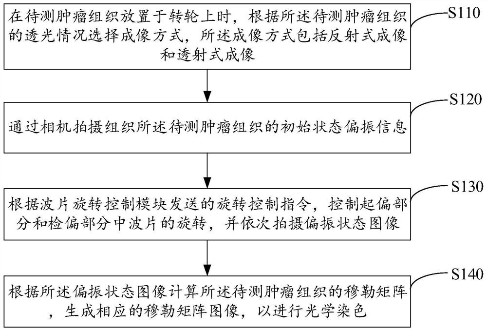
[0048] attached image 3 It is a flow chart of the implementation of the tumor tissue imaging method shown in the second embodiment. The tumor tissue imaging method shown in Embodiment 2 is applicable to a tumor tissue imaging device. For ease of description, only the parts related to the embodiments of the present invention are shown, and the details are as follows:

[0049] Step S110, when the tumor tissue to be tested is placed on the rotating wheel, an imaging mode selected according to the light transmission of the tumor tissue to be tested is received, and the imaging mode includes reflection imaging and transmission imaging.

[0050] In step S120, the initial state polarization information of the tumor tissue to be tested is captured by a camera.

[0051] Step S130, according to the rotation control command sent by the wave plate rotation control module, control the rotation of the wave plate in the polarizer and the analyzer, and sequentially capture images of polari...


PUM


Abstract

The invention is applicable to the technical field of biological tissue imaging, and provides a tumor tissue imaging device and method. The tumor tissue imaging device comprises a light source, a polarizing part, a rotating wheel, a polarization analyzing part and a camera, wherein the light source, the polarizing part, the polarization analyzing part and the camera are distributed in a light pathdirection, and the rotating wheel is located between the polarizing part and the polarization analyzing part; and the rotating wheel is used for enabling the polarizing part or the polarization analyzing part to rotate according to a preset angle so as to switch imaging modes, and the imaging modes comprise reflection type imaging and transmission type imaging. Compared with an existing stainingtechnology, the requirement for pretreatment of tumor tissue to be detected is not high, the limitation on the size, the form and the light transmission of the tumor tissue to be measured is smaller,the measurement objects are wider, switching between the transmission type and reflection type can be freely realized, and the use flexibility and the applicability of the device are effectively improved.

Description

technical field [0001] The invention belongs to the technical field of polarization imaging, and in particular relates to a tumor tissue imaging device and method. Background technique [0002] The observation of tumor tissue in clinical practice generally adopts the form of stained section microscope observation. Part of the diseased tissue or organ needs to be taken, fixed and hardened after treatment, sectioned and stained, and the pathological changes are observed through an optical microscope, and the pathologist reads the slides Make a pathological diagnosis. Due to the different properties of tissues or cells, tissues with different components have different affinities to dyes, and different tissues have different color expressions after staining, so that pathologists can judge the pathological conditions of tumor tissues after staining. [0003] Polarization is one of the four inherent properties of light. Due to the insensitivity of human eyes to polarization, the ...

Claims


Application Information

Patent Timeline
Patent Type & Authority Applications(China)
IPC IPC(8): A61B5/00
CPCA61B5/0059
Inventor 黄丹飞钟艾琦姜会林
Owner CHANGCHUN UNIV OF SCI & TECH
Why Eureka
Try Eureka