Solid waste decoupling combustion device, solid waste decoupling combustion system device and combustion method of solid waste decoupling combustion device

A combustion device and channel technology, which is applied in the field of solid waste decoupling combustion devices, can solve the problems of being unsuitable for small and medium-sized devices, occupying a large area, and complicated in process, so as to reduce temperature fluctuations, reduce high-temperature slagging, and improve laminar combustion. The effect of zone temperature

Pending Publication Date: 2021-06-01
INST OF PROCESS ENG CHINESE ACAD OF SCI +1
View PDF12 Cites 2 Cited by
  • Summary
  • Abstract
  • Description
  • Claims
  • Application Information

AI Technical Summary

Problems solved by technology

The present invention realizes the purpose of low energy consumption, cleanliness, recycling and harmless treatment of high-moisture organic solid waste by drying tail gas after harmless treatment, but it has complex structure, complicated process and occupied area Large and other problems, not suitable for small and medium-sized devices that deal with dispersed solid waste

Method used


Image

  • Solid waste decoupling combustion device, solid waste decoupling combustion system device and combustion method of solid waste decoupling combustion device
  • Solid waste decoupling combustion device, solid waste decoupling combustion system device and combustion method of solid waste decoupling combustion device

Examples


Embodiment 1

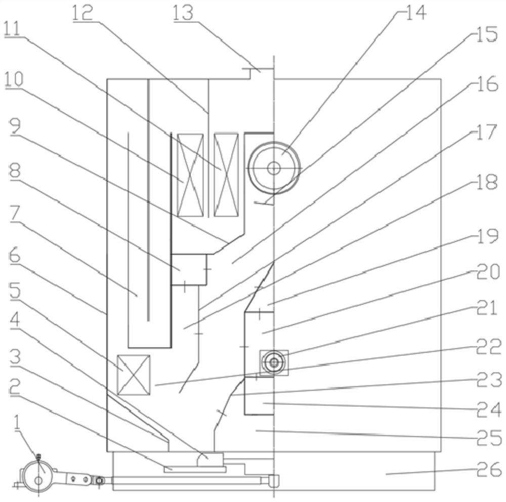
[0116] This embodiment provides a solid waste decoupling combustion system device, such as figure 1 As shown, based on the combustion system device described in a specific embodiment, wherein, two solid waste decoupling combustion devices are symmetrically arranged in the combustion system device, and the material of the heat-resistant metal is 310S, 316L, 304 or 1Cr18Ni9Ti, and the rest of the structure is the same as The combustion system devices described in a specific embodiment are identical.

[0117] This embodiment also provides a method for burning materials using the above-mentioned solid waste decoupling combustion system device, based on the combustion method described in a specific embodiment, wherein the temperature of the gas in the hot air chamber 19 in step (II) is 400°C; the gas entering the preheating drying zone in the hot air chamber 19 accounts for 70% of the total gas volume; the temperature of the gas in the auxiliary heating air chamber 20 is 500°C; the...

Embodiment 2

[0119] This embodiment provides a solid waste decoupling combustion system device, based on the combustion system device described in a specific embodiment, wherein the combustion system device includes three solid waste decoupling combustion devices, and the material of the heat-resistant metal is 316L , the rest of the structure is exactly the same as the combustion system device described in a specific embodiment.

[0120] This embodiment also provides a method for burning materials using the above-mentioned solid waste decoupling combustion system device, based on the combustion method described in a specific embodiment, wherein the temperature of the gas in the hot air chamber 19 in step (II) is 200°C; the gas entering the preheating drying zone in the hot air chamber 19 accounts for 50% of the total gas volume; the temperature of the gas in the auxiliary heating air chamber 20 is 700°C; the temperature in the flue gas co-combustion channel 22 is 1300°C; step (Ⅲ ) The tim...

Embodiment 3

[0122] This embodiment provides a solid waste decoupling combustion system device, based on the combustion system device described in a specific embodiment, wherein the combustion system device includes four solid waste decoupling combustion devices, and the material of the heat-resistant metal is 1Cr18Ni9Ti , the rest of the structure is exactly the same as the combustion system device described in a specific embodiment.

[0123] This embodiment also provides a method for burning materials using the above-mentioned solid waste decoupling combustion system device, based on the combustion method described in a specific embodiment, wherein the temperature of the gas in the hot air chamber 19 in step (II) is 600°C; the gas entering the preheating drying zone in the hot air chamber 19 accounts for 90% of the total gas volume; the temperature of the gas in the auxiliary heating air chamber 20 is 100°C; the temperature in the flue gas co-combustion channel 22 is 800°C; step (Ⅲ ) The...


PUM


Abstract

The invention provides a solid waste decoupling combustion device, a solid waste decoupling combustion system device and a combustion method of the solid waste decoupling combustion device. The combustion device comprises a shell, wherein the interior of the shell is divided into a feeding combustion channel, a flue gas mixed combustion channel and a flue gas afterflame channel which are sequentially communicated through partition plates in the material flowing direction, and the feeding combustion channel is divided into a preheating drying area, a pyrolysis gasification area, a semi-coke area and a burnout area in the material flowing direction; an air distribution device is arranged below the feeding end in the feeding combustion channel, and vent holes are formed in the outer wall of the side, close to the preheating drying area and the pyrolysis gasification area, of the air distribution device; at least one deflection baffle is arranged in the flue gas afterflame channel, and a rotary deflection flue gas flow channel is formed in the flue gas afterflame channel through the deflection baffles; and an air-smoke heat exchanger is arranged in the flue gas afterflame channel close to the outlet. Through the reasonable flue and air distribution design and the optimized combustion process, materials are fully combusted, and the combustion device has the advantages of being compact in structure, small in pollutant emission and the like.

Description

technical field [0001] The invention belongs to the technical field of solid waste treatment, and relates to a solid waste decoupling combustion device, in particular to a solid waste decoupling combustion device, a combustion system device and a combustion method thereof. Background technique [0002] Low calorific value solid waste includes industrial solid waste containing organic matter, sludge and various types of garbage. The components of this type of low-calorific value solid waste are complex and changeable, and there are many problems, such as high water content, many solid non-combustible components, difficult to decompose, difficult to ignite and difficult to burn out, etc., making the theoretical combustion temperature of this type of solid waste low and the ignition time Long, poor combustion stability, not easy to burn out. With the traditional combustion method, the flue gas contains a large amount of pollutants such as dioxins and tars that have not been fu...

Claims


Application Information

Patent Timeline
Patent Type & Authority Applications(China)
IPC IPC(8): F23G5/027F23G5/04F23G5/08F23G5/44F23G5/50
CPCF23G5/027F23G5/04F23G5/08F23G5/44F23G5/50
Inventor 郝江平高士秋余剑赵康刘周恩李剑玲
Owner INST OF PROCESS ENG CHINESE ACAD OF SCI
Why Eureka
Try Eureka