
Suspension device for aluminum alloy profile spraying and spraying method

A technology of aluminum alloy profiles and suspension devices, applied in the direction of spraying devices, can solve problems such as poor spraying effect and increase cost, and achieve the effects of increasing friction, increasing contact area, and increasing the scope of application

Pending Publication Date: 2020-12-04
肖述虎
View PDF11 Cites 0 Cited by
  • Summary
  • Abstract
  • Description
  • Claims
  • Application Information

AI Technical Summary

Problems solved by technology

The suspension device in the above patent cannot rotate the part to be sprayed, and spray guns need to be installed on all sides to spray in all directions, which increases the cost and poor spray effect

Method used


Image

  • Suspension device for aluminum alloy profile spraying and spraying method
  • Suspension device for aluminum alloy profile spraying and spraying method
  • Suspension device for aluminum alloy profile spraying and spraying method

Examples


Embodiment 1

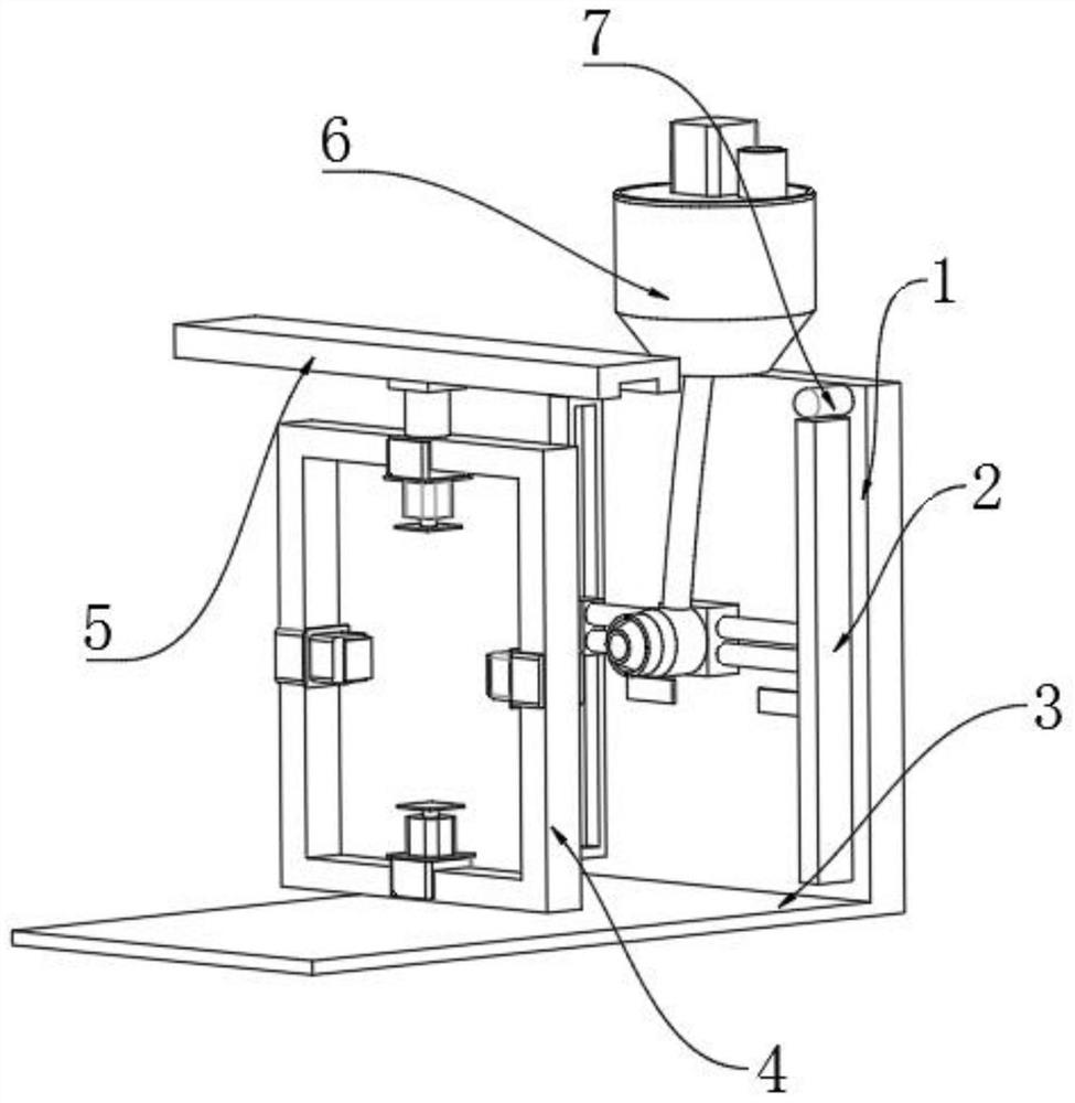
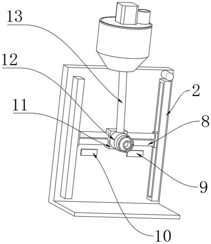
[0038] A suspension device for spraying aluminum alloy profiles, in order to speed up the purification of water, such as figure 2 , Figure 4 , Figure 7As shown, it includes a support plate 1; the outer wall of the bottom end of the support plate 1 is fixedly connected with a bottom plate 3 by screws; a transmission electric guide rail 5 is arranged above the bottom plate 3; an electric slider 14 is slidingly connected to the inner wall of one side of the transmission electric guide rail 5; The outer wall on one side of the slider 14 is fixedly connected with a fixed frame 4 by screws; the upper and lower inner walls of the fixed frame 4 are connected with a longitudinal electric push rod 20 by bolts; the outer wall on one side of the output shaft of the vertical electric push rod 20 is fixed and connected with a push plate 16. The outer wall on one side of the push plate 16 is connected with a longitudinal servo motor 17 by bolts; There is a horizontal servo motor 19; the...

Embodiment 2

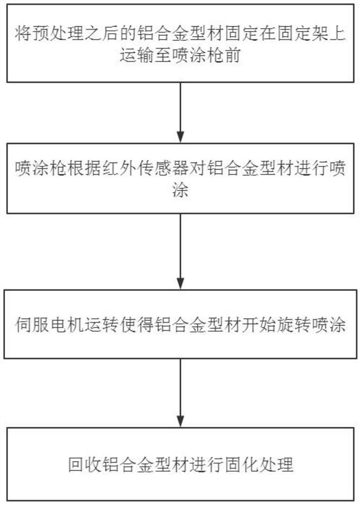
[0045] A spraying method of the suspension device for aluminum alloy profile spraying according to Embodiment 1, such as figure 1 shown, including the following steps:

[0046] S1: Fix the pretreated aluminum alloy profile on the first electric guide rail 2 and transport it to the spray gun 12;

[0047] S2: the spraying gun 12 sprays the aluminum alloy profile according to the infrared sensor 23;

[0048] S3: The rotation of the servo motor makes the aluminum alloy profile start to rotate and spray;

[0049] S4: Recycling aluminum alloy profiles for curing.

[0050] When this embodiment is in use, turn on the power supply of various electrical equipment, first push the fixing plates 18 on the upper and lower sides through the longitudinal electric push rod 20 to fix the aluminum alloy profile, and now the horizontal electric push rod 15 is in a contracted state. After the block 14 transports the aluminum alloy profiles to the designated location, the aluminum alloy profiles...


PUM


Abstract

The invention discloses a suspension device for aluminum alloy profile spraying and a spraying method, and relates to the technical field of suspension spraying. The problem that an aluminum alloy profile cannot be sprayed in all directions is solved. The method specifically comprises the following steps that a pretreated aluminum alloy profile is fixed to a first electric guide rail and transported to the position in front of a spraying gun, the spraying gun sprays the aluminum alloy profile according to an infrared sensor, a servo motor operates and enables the aluminum alloy profile to start rotating spraying, and the aluminum alloy profile is recycled for curing treatment. Electric push rods are arranged on a fixing frame, firstly, the longitudinal electric push rods push fixing plateson the upper side and the lower side to fix the aluminum alloy profile, at the moment, the transverse electric push rods are in a contraction state, the contact area with the aluminum alloy profile is increased through the fixing plates, and therefore friction force is improved, the fixing effect of the aluminum alloy profile is better, the suspension device can fix the aluminum alloy profile with complex shapes, and the application range of the device is widened.

Description

technical field [0001] The invention relates to the technical field of suspension spraying, in particular to a suspension device and a spraying method for aluminum alloy profile spraying. Background technique [0002] In order to enhance the performance of aluminum alloy profiles and improve the service life of aluminum alloy profiles, thermosetting powder coatings are generally sprayed on aluminum alloy profiles. Thermosetting powder coatings have low melt viscosity, good leveling, and form a non-melting coating film after crosslinking, which is very Applicable to the anti-corrosion or decorative workpiece surface with high performance and technical requirements. At present, in the existing technology, the suspension device of aluminum alloy profiles is generally a hanging hook. It is necessary to install spray guns on all sides to fully spray aluminum alloy profiles. Spraying increases the cost, and the spraying effect is poor. Therefore, there is an urgent need for a susp...

Claims


Application Information

Patent Timeline
Patent Type & Authority Applications(China)
IPC IPC(8): B05B12/02B05B12/12B05B13/02B05B13/04B05B15/25
CPCB05B12/02B05B12/12B05B12/122B05B12/124B05B13/0228B05B13/0264B05B13/0442B05B15/25
Inventor 肖述虎
Owner 肖述虎
Learn More