PCD forming sleeve milling cutter

A technology of forming sleeves and milling cutters, which is applied in the direction of milling cutters, milling machine equipment, manufacturing tools, etc., can solve the problems of inconvenient cutting, reducing the overall rigidity of the cutting tool, and scratches on the workpiece surface, so as to reduce the possibility of cutter vibration and solve the problem of Insufficient cutting space, good rigidity and structural strength

Pending Publication Date: 2020-12-04
BEIJING WORLDIA DIAMOND TOOLS
View PDF0 Cites 2 Cited by
  • Summary
  • Abstract
  • Description
  • Claims
  • Application Information

AI Technical Summary

Problems solved by technology

When processing the outer contours of some workpieces with narrow spatial structures (such as parts in automobile turbochargers), in order to avoid the impact of the milling cutter's tool movement by the spatial structure, the outer contour dimensions of the milling cutter will be made It is very small, but this reduces the overall rigidity of the tool, and it is easy to vibrate the tool when using it, which may easily cause the surface of the workpiece to be scratched
[0004] For the convenience of understanding, here is a brief introduction to the above mentioned workpieces with narrow space structure, refer to image 3 , the workpiece at least includes a base 4 and a first connecting part 5 and a second connecting part 6 formed on the base, the space between the first connecting part 5 and the second connecting part 6 is relatively narrow, and it is inconvenient to move the tool
[0005] In view of the above-mentioned related technologies, the inventor believes that when processing the outer contour of a workpiece with a narrow spatial structure, in order to avoid the obstruction of the milling cutter by the spatial structure, the outer contour of the milling cutter is made very small. It is easy to cause the surface of the workpiece to be scratched due to the vibrating tool

Method used


Image

  • PCD forming sleeve milling cutter
  • PCD forming sleeve milling cutter
  • PCD forming sleeve milling cutter

Examples


Embodiment Construction

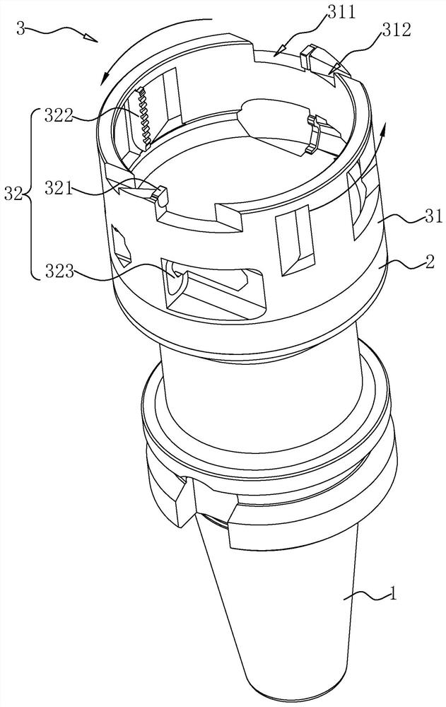
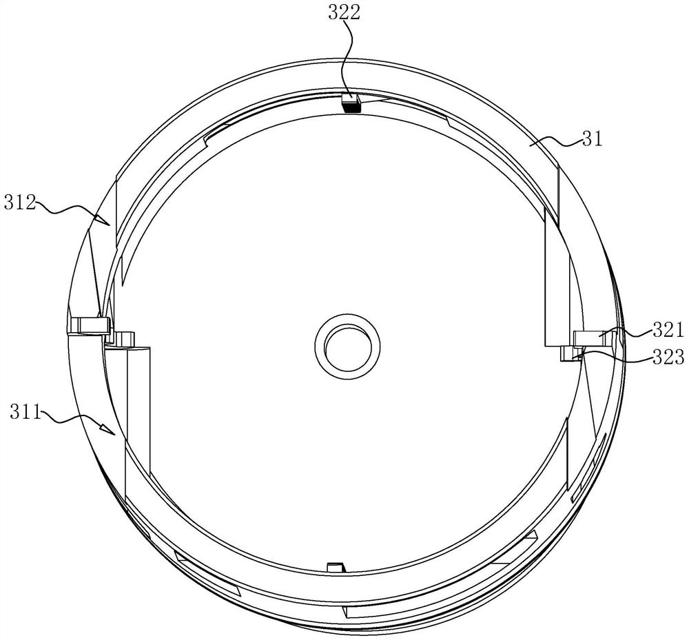
[0028] The following is attached Figure 1-2 The application is described in further detail.

[0029] The embodiment of the present application discloses a PCD forming sleeve milling cutter, refer to figure 1 , including a knife handle 1, a knife neck platform 2 and a knife head 3, and the three are arranged in sequence. More specifically, the knife handle 1 can be a BT30 knife handle, the knife neck platform 2 is integrally formed at one end of the knife handle 1 , and the knife head 3 is fixed on the side of the knife neck platform 2 away from the knife handle 1 .

[0030] The cutter head 3 includes an annular tool rest 31 fixed on the knife neck platform 2 and a cutter body 32 installed on the inner wall of the annular tool rest 31. The diameter of the annular tool rest 31 is greater than the diameter of the workpiece to be processed. Specifically, the annular tool rest 31 The size of the rotating ring can enter the limited space of the workpiece to be processed without ...


PUM


Abstract

The invention relates to the technical field of milling cutters, in particular to a PCD forming sleeve milling cutter. The cutter comprises a cutter handle, a cutter neck platform formed at one end ofthe cutter handle and a cutter head fixedly connected to the side, away from the cutter handle, of the cutter neck platform. The cutter head comprises an annular cutter rest fixedly connected to thecutter neck platform and used for being arranged outside a to-be-machined workpiece in a sleeving manner, and a cutter body installed on the inner wall of the annular cutter rest. The milling cutter has the effects that the outer contour of the workpiece of a narrow space structure can be conveniently machined, and meanwhile, the possibility of cutter vibration is reduced to reduce scratches on the surface of the workpiece.

Description

technical field [0001] The present application relates to the technical field of milling cutters, in particular to a PCD forming sleeve milling cutter. Background technique [0002] A milling cutter is a rotating tool with one or more teeth for milling operations. It is mainly used for machining planes, steps, grooves, forming surfaces and cutting off workpieces on milling machines. [0003] When the outer contour of the workpiece is processed, winding milling is used, and the method of winding milling requires that the edge of the milling cutter is consistent with the outer contour of the workpiece. When processing the outer contours of some workpieces with narrow spatial structures (such as parts in automobile turbochargers), in order to avoid the impact of the milling cutter's tool movement by the spatial structure, the outer contour dimensions of the milling cutter will be made It is very small, but this reduces the overall rigidity of the tool, and it is easy to vibra...

Claims


Application Information

Patent Timeline
Patent Type & Authority Applications(China)
IPC IPC(8): B23C5/00
CPCB23C5/00B23C2210/48
Inventor 闫文森李克坤
Owner BEIJING WORLDIA DIAMOND TOOLS
Why Eureka
Try Eureka