
Precise guide rail part machining tool convenient to clamp

A kind of parts processing and precise technology, applied in the field of precision guide rail parts processing tooling, can solve the problems of easy accumulation of processing waste and inconvenient clamping of processing tooling, etc., achieve simple and convenient clamping operation, improve convenience, and avoid accumulation of waste Effect

Inactive Publication Date: 2020-12-04
马鞍山铭成科技信息咨询有限公司
View PDF0 Cites 0 Cited by
  • Summary
  • Abstract
  • Description
  • Claims
  • Application Information

AI Technical Summary

Problems solved by technology

[0004] The purpose of the present invention is to solve the problems of inconvenient clamping and easy accumulation of processing waste in the prior art, and propose a precision guide rail parts processing tool that is easy to clamp

Method used


Image

  • Precise guide rail part machining tool convenient to clamp
  • Precise guide rail part machining tool convenient to clamp
  • Precise guide rail part machining tool convenient to clamp

Examples


Embodiment Construction

[0024] Next, the technical solutions in the embodiments of the present invention will be described in connection with the drawings of the embodiments of the present invention, and it is understood that the described embodiments are merely the embodiments of the present invention, not all of the embodiments.

[0025] In the description of the present invention, it is to be understood that the terms "upper", "lower", "front", "post", "left", "right", "top", "bottom", "inside", " The orientation or position of the instructions such as "is based on the orientation or positional relationship shown in the drawings, which is merely intended to describe the present invention and simplified description, rather than indicating or implying that the device or component must have a specific orientation. Specific orientation configurations and operations are not to be understood as limiting the invention.

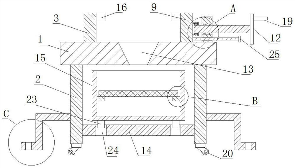
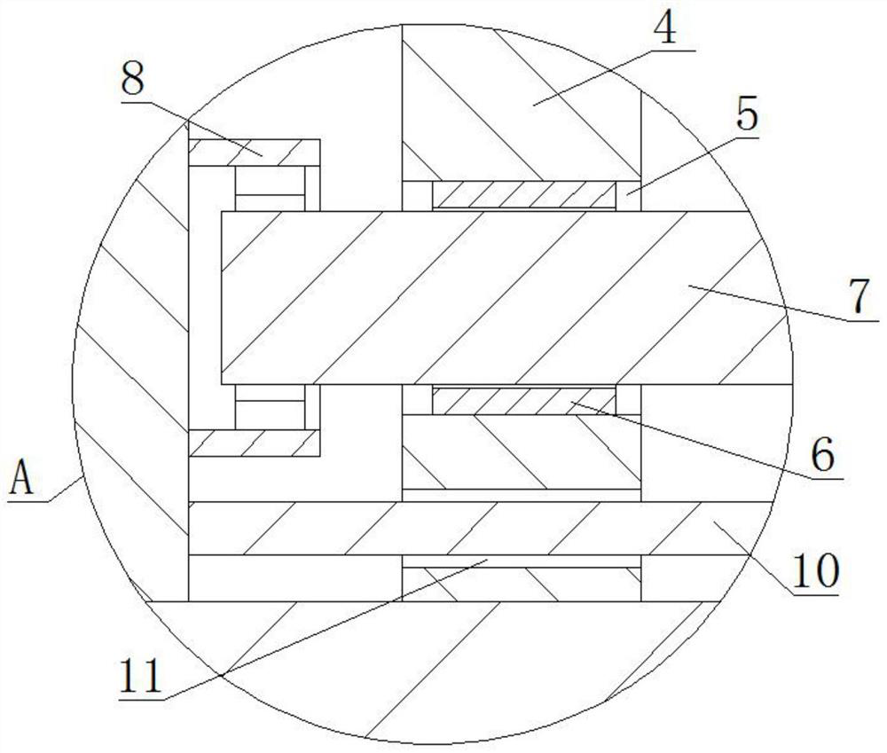
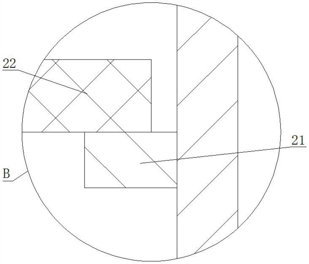
[0026] Refer Figure 1-4 A system for facilitating precise clamping rail tooling parts pr...


PUM


Abstract

The invention relates to the technical field of machining tools, and discloses a precise guide rail part machining tool convenient to clamp. The precise guide rail part machining tool comprises a workbench; the four corners of the lower surface of the workbench are each fixedly connected with a supporting leg; a first clamping plate is fixedly connected to the sidewall of the upper side of the workbench; a fixed plate is fixedly connected to the sidewall of the upper side of the workbench; the fixed plate is located on the right side of the first clamping plate; a fixing hole is formed in thesidewall of the right side of the fixed plate; a threaded sleeve is fixedly connected inside the fixing hole; an adjusting screw rod is connected inside the threaded sleeve by screw threads; the two ends of the adjusting screw rod both extend out of the fixing hole; the left end of the adjusting screw rod is sleeved with a sleeve; and the inner wall of the sleeve is rotationally connected with theadjusting screw rod through a bearing. The precise guide rail part machining tool disclosed by the invention is simple and convenient in clamping operation, effectively improves the use convenience and effectively prevents the problem that waste fragments are easily accumulated on an existing tool.

Description

Technical field [0001] The present invention relates to tooling and processing technology, and particularly relates to an easy clamping rail parts processing precision tooling. Background technique [0002] Rail transport is an important part of the rail, the rail when the tooling required for production and processing of the fixed guide rail, the guide rail so as to avoid the movement generated during processing, improve the accuracy of machining the guide rail. [0003] Conventional machining tooling guide in use, the clamping rail is inconvenient, people need to work together to perform operations tooling fixture, the clamping operation is more complicated and inconvenient, and conventional tooling scrap during machining directly generated using deposited on the tooling, easily affect the normal working of the rail. Inventive content [0004] Object of the present invention is to solve the problems of the prior art machining and processing inconvenience tooling fixture scrap ...

Claims


Application Information

Patent Timeline
Patent Type & Authority Applications(China)
IPC IPC(8): B23Q3/06B23Q11/00B23Q1/01
CPCB23Q1/01B23Q3/062B23Q11/0067
Inventor 陈君明
Owner 马鞍山铭成科技信息咨询有限公司
Learn More