Automatic lifting hydraulic movable water retaining dam based on PLC control

An automatic lifting and movable gear technology, which is applied in water conservancy projects, sea area projects, coastline protection, etc., can solve problems such as leakage of hydraulic telescopic rods, achieve the effect of ensuring service life and avoiding damage to electrical components

Inactive Publication Date: 2020-12-04
安徽金川活动坝科技有限公司
View PDF9 Cites 2 Cited by
  • Summary
  • Abstract
  • Description
  • Claims
  • Application Information

AI Technical Summary

Problems solved by technology

[0004] Aiming at the deficiencies of the prior art, the present invention provides a PLC-based automatic lifting hydraulic movable retaining dam, which solves the problem that the existing hydraulic retaining dams use hydraulic telescopic rods to prop up the main board of the retaining dam to achieve the water retaining effect, and the impact The force is basically fully borne by the hydraulic telescopic rod. After a long time of use, the hydraulic telescopic rod may leak

Method used


Image

  • Automatic lifting hydraulic movable water retaining dam based on PLC control
  • Automatic lifting hydraulic movable water retaining dam based on PLC control
  • Automatic lifting hydraulic movable water retaining dam based on PLC control

Examples


Embodiment Construction

[0030] The following will clearly and completely describe the technical solutions in the embodiments of the present invention with reference to the accompanying drawings in the embodiments of the present invention. Obviously, the described embodiments are only some, not all, embodiments of the present invention. Based on the embodiments of the present invention, all other embodiments obtained by persons of ordinary skill in the art without making creative efforts belong to the protection scope of the present invention.

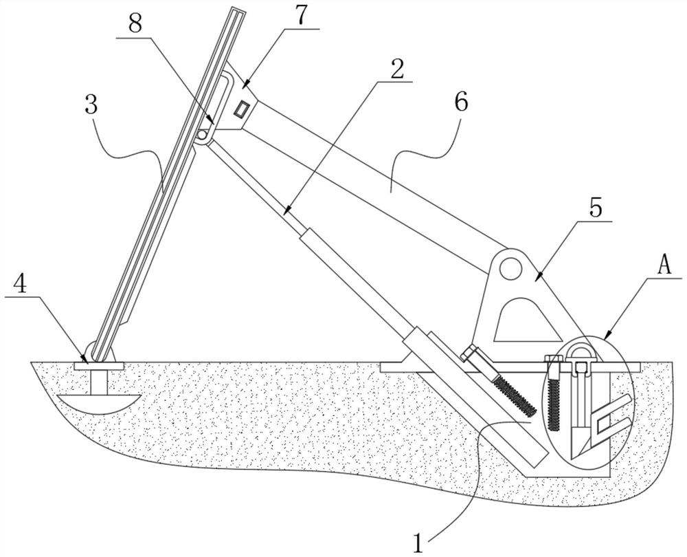
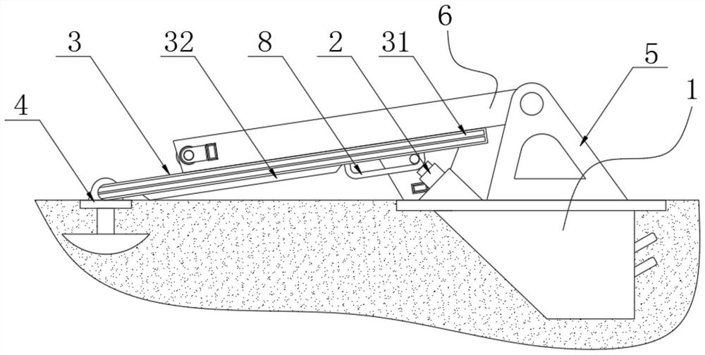
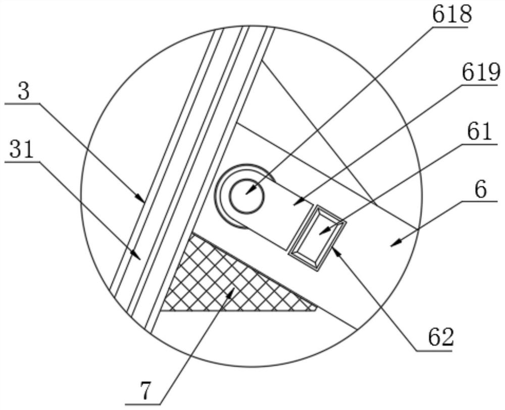
[0031] see Figure 1-8, the present invention provides a technical solution: a PLC-based automatic lifting hydraulic movable retaining dam, including a hydraulic mechanism base 1, a hydraulic rod 2 and a water retaining plate 3, and the bottom of the water retaining plate 3 passes through a hinge seat 4 Rotately connected with the ground, the front and rear sides of the water retaining plate 3 are fixedly connected with sealing rubber strips 31, the right side...


PUM


Abstract

The invention discloses an automatic lifting hydraulic movable water retaining dam based on PLC control, and relates to the technical field of water retaining dams. The dam comprises a hydraulic mechanism base, a hydraulic rod and a water retaining plate, wherein the bottom of the water retaining plate is rotatably connected to the ground through a hinge base, a main sleeve of the hydraulic rod isfixedly connected to the interior of the hydraulic mechanism base, a supporting base is fixedly connected to the top of the hydraulic mechanism base, According to the automatic lifting hydraulic movable water retaining dam based on the PLC control, a hydraulic cylinder used for supporting in a traditional hydraulic movable dam is changed into a hydraulic cylinder only used for pushing, supportingis borne by supporting square steel, the supporting square steel is erected on the water retaining plate in the state that the water retaining plate is put down, after the water retaining plate is supported by the hydraulic rod, the supporting square steel can be automatically erected on the supporting base on the right side of the water retaining plate, the supporting effect can be achieved after the supporting square steel matches a square pin for fixing, the supporting square steel is used for supporting, and compared with the hydraulic rod, larger force can be borne, so that the movable dam can bear larger water flow impact force.

Description

technical field [0001] The invention relates to the technical field of retaining dams, in particular to a PLC-based automatic lifting hydraulic movable retaining dam. Background technique [0002] Retaining dams are used for agricultural irrigation, fishery, ship locks, seawater tides, urban river landscapes, engineering, hydropower stations, and the world's leading movable dam technology. Retaining dam is the world's leading movable dam technology, which is used in agricultural irrigation, fishery, ship lock, seawater tidal protection, urban river landscape, engineering, hydropower station, hinge movable dam has scientific mechanical structure, no water blocking, no fear of sedimentation, and no floating It overcomes all the shortcomings of the traditional movable dam type, and has all the advantages of the traditional dam type. [0003] Chinese patents such as the retaining dam disclosed in CN206521737U, and a kind of self-supporting double-sided hydraulic lifting dam dis...

Claims


Application Information

Patent Timeline
IPC IPC(8): E02B7/40
CPCE02B7/40
Inventor 陈勤平
Owner 安徽金川活动坝科技有限公司
Why Eureka
Try Eureka