Transverse socket and spigot joint suitable for prefabricated underground diaphragm wall

An underground diaphragm wall and prefabricated assembly technology, applied in sheet pile wall, construction, infrastructure engineering and other directions, can solve the problems of no longer meeting the requirements of green environmental protection development, low operation efficiency, large consumption of raw materials, etc., to control the construction quality and The effect of component strength, accurate horizontal position and simple construction process

Pending Publication Date: 2020-12-04
CHINA TIESIJU CIVIL ENG GRP CO LTD +1
View PDF0 Cites 1 Cited by
  • Summary
  • Abstract
  • Description
  • Claims
  • Application Information

AI Technical Summary

Problems solved by technology

For the current conventional construction of the underground diaphragm wall, concrete is poured on site, which also leads to problems such as low operating efficiency, large consumption of raw materials, and serious environmental pollution on site, which no longer meets the development requirements of today's society for green environmental protection.
With the introduction of national policy orientation and preferential policies for prefabricated structures in recent years, the prefabricated construction of underground diaphragm walls has also been adopted in more and more places, and for deep and large foundation pit prefabricated underground diaphragm walls, its The height of the structure is limited by the on-site construction capacity. It is often necessary to lift and install the prefabricated underground diaphragm wall in sections. The construction process of the common prefabricated diaphragm wall is complicated and the efficiency is low.

Method used


Image

  • Transverse socket and spigot joint suitable for prefabricated underground diaphragm wall
  • Transverse socket and spigot joint suitable for prefabricated underground diaphragm wall
  • Transverse socket and spigot joint suitable for prefabricated underground diaphragm wall

Examples


Embodiment Construction

[0019] The following will clearly and completely describe the technical solutions in the embodiments of the present invention with reference to the accompanying drawings in the embodiments of the present invention. Obviously, the described embodiments are only some, not all, embodiments of the present invention. Based on the embodiments of the present invention, all other embodiments obtained by persons of ordinary skill in the art without making creative efforts belong to the protection scope of the present invention.

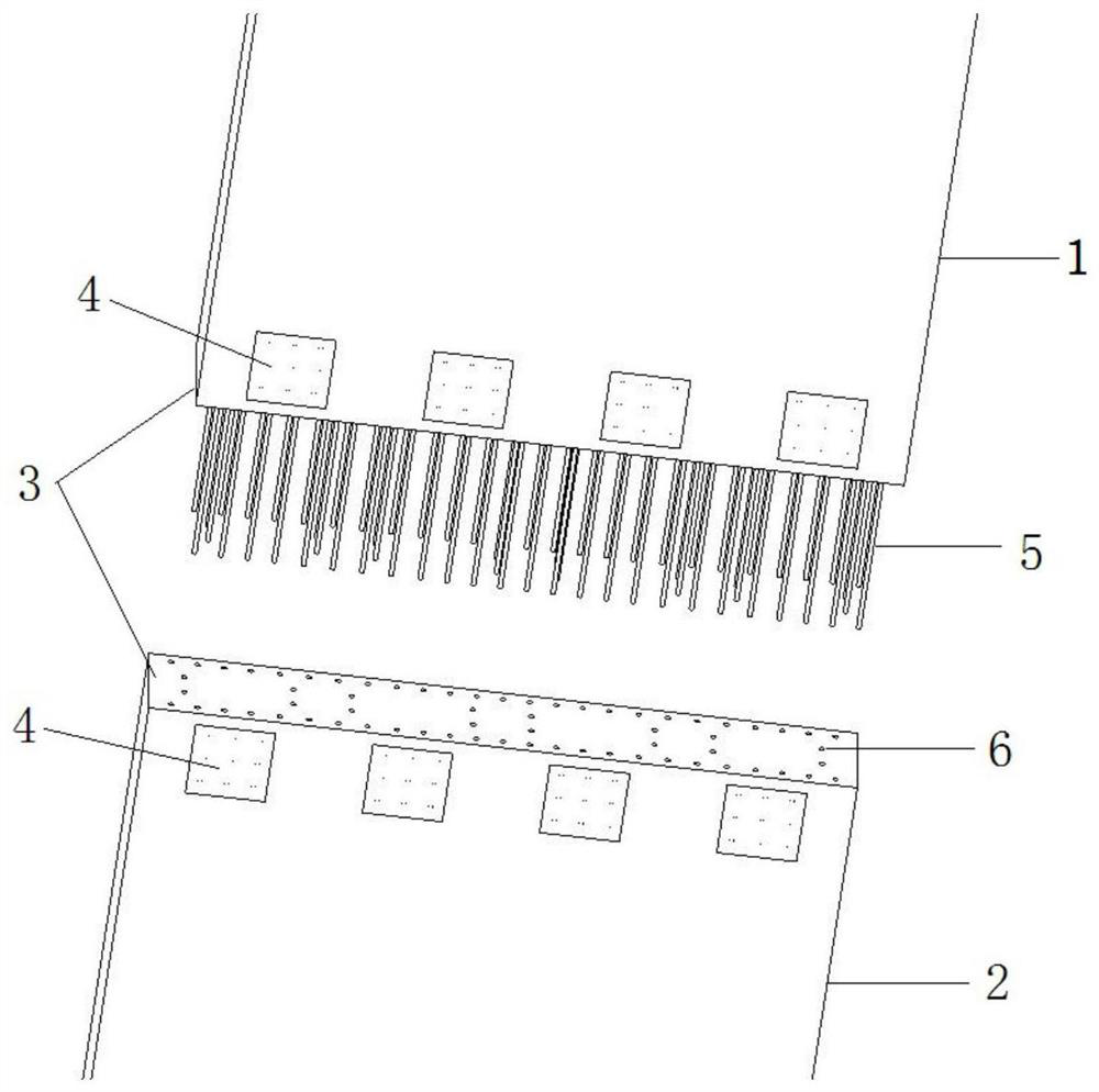
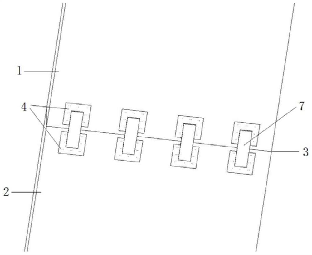
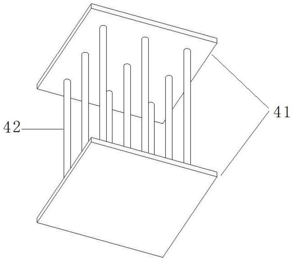
[0020] see Figure 1-5 , in an embodiment of the present invention, a transverse socket joint suitable for a prefabricated underground diaphragm wall, the diaphragm wall includes an upper section 1, a lower section 2 and when the upper section 1 and the lower section 2 are fixed The interconnected joint surface 3 includes first fixing means for laterally fixing the upper section 1 and the lower section 2, which is arranged on the side connected to the longer s...


PUM


Abstract

The invention discloses a transverse socket and spigot joint suitable for a prefabricated underground diaphragm wall. The transverse socket and spigot joint comprises a first fixing device and a second fixing device, wherein the first fixing device is arranged on the side surface of the wider side of a splicing surface and used for transversely fixing an upper section and a lower section, the first fixing device comprises counter-pull embedded parts and connecting steel plates arranged on the surfaces of the counter-pull embedded parts at the opposite positions of the upper section and the lower section, the second fixing device is arranged on the splicing surface and is used for longitudinally fixing the upper section and the lower section, and the second fixing device comprises connecting pieces arranged on the splicing surface of the upper section and holes formed in the splicing surface of the lower section and used for allowing the connecting pieces to be placed. The transverse socket and spigot joint is simple in structure, the construction quality and the component strength can be effectively controlled, the construction process is simple, the construction efficiency is high, the horizontal position is effectively ensured to be accurate after the upper section and the lower section of the wall are in butt joint, and the waterproof function of wall joints is achieved.

Description

technical field [0001] The invention relates to the field of underground diaphragm walls, in particular to a transverse socket joint suitable for prefabricated underground diaphragm walls. Background technique [0002] In recent years, the development and utilization of underground space has become the driving force of urban development and the growth point of economic prosperity. During the construction of large underground structures such as underground rail transit and underground living squares, the underground continuous wall can not only be used as an anti-seepage retaining wall The body can be regarded as a part of the main body of the structure and play an irreplaceable role. For the current conventional construction of the underground diaphragm wall, concrete is poured on site, which also leads to problems such as low operating efficiency, large consumption of raw materials, and serious environmental pollution on site, which no longer meets the development requireme...

Claims


Application Information

Patent Timeline
Patent Type & Authority Applications(China)
IPC IPC(8): E02D5/10E02D5/12E02D5/14
CPCE02D5/10E02D5/12E02D5/14
Inventor 王坤为欧林果李永贵孙昆鹏张鹤蒋明星曹章平黄大明黄栩邱宝玉苏朋辉
Owner CHINA TIESIJU CIVIL ENG GRP CO LTD
Why Eureka
Try Eureka