
Metering, testing and control method for internal pressure reduction flowing characteristic of labyrinth disc pressure reducing valve

A measurement test and flow characteristic technology, applied in valve devices, engine components, mechanical equipment, etc., can solve the problems of regulation lag, low control accuracy, lack of quantitative measurement test methods for depressurized flow characteristics, etc. high precision effect

Active Publication Date: 2020-12-04
ZHEJIANG SCI-TECH UNIV +1
View PDF7 Cites 1 Cited by
  • Summary
  • Abstract
  • Description
  • Claims
  • Application Information

AI Technical Summary

Problems solved by technology

However, the existing research is mainly based on numerical simulation, and there is a lack of accurate quantitative measurement and testing methods for the pressure-reducing flow characteristics in the flow channel of the labyrinth valve spool. The control accuracy of the labyrinth valve based on numerical simulation is not high, and the regulation lags behind. The problem

Method used


Image

  • Metering, testing and control method for internal pressure reduction flowing characteristic of labyrinth disc pressure reducing valve
  • Metering, testing and control method for internal pressure reduction flowing characteristic of labyrinth disc pressure reducing valve
  • Metering, testing and control method for internal pressure reduction flowing characteristic of labyrinth disc pressure reducing valve

Examples


Embodiment Construction

[0046] The present invention will be further described below in conjunction with the accompanying drawings and embodiments.

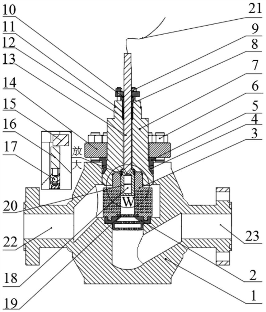
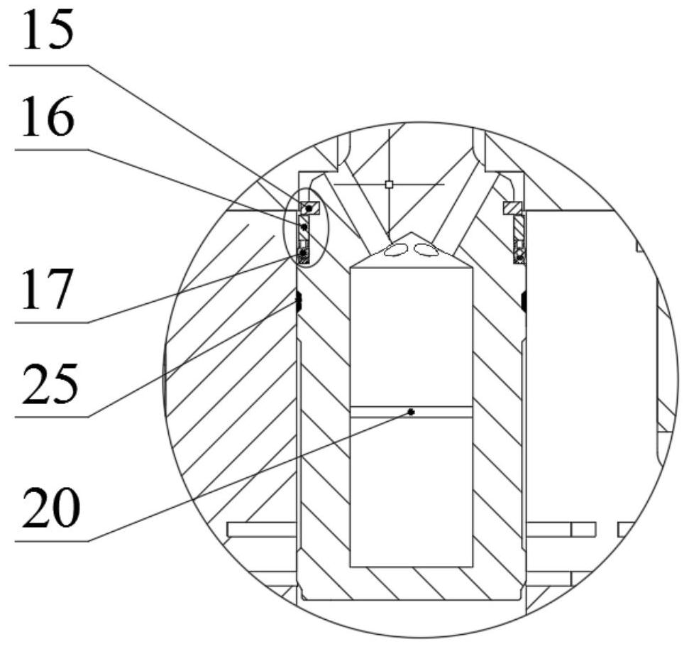
[0047] Such as figure 1 , figure 2 As shown, the specific implementation of the labyrinth disc pressure reducing valve includes a valve body 1, a valve seat 2, a labyrinth disc sleeve 3, a valve cover 7, a valve stem 13, a valve core 18, a throttle orifice 19 and a valve stem position regulator 21. A circular opening is set on the top of the valve body 1, and a valve cover 7 is installed in the circular opening. A central through hole is opened in the vertical direction inside the valve cover 7. An upper cavity and a lower cavity are provided inside the valve body. There is a horizontal medium inlet 22 and a medium outlet 23 at the side end, the medium inlet 22 communicates with the upper cavity of the valve body 1, and the medium outlet 23 communicates with the lower cavity of the valve body 1; The hole is connected, and the valve seat 2 is installe...


PUM


Abstract

The invention discloses a metering, testing and control method for internal pressure reduction flowing characteristic of a labyrinth disc pressure reducing valve. The metering, testing and control method comprises the following steps: a circulating pipeline loop is built, a labyrinth disc pressure reducing valve is installed, and water flushing and pressurizing are conducted; the circulating pipeline loop is divided into a plurality of sections of sub-runners, and a pressure strain gauge and a flow meter are mounted on a longitudinal cross section; detection is carried out to obtain a pressurevalue and a flow rate value; a harmonic average value is calculated; discrete curves of harmonic average values, varying along with inlet pressure, at different cross sections are drawn; energy dissipation maps corresponding to different inlet pressures are drawn; interpolation calculation is carried out; a critical energy dissipation value is determined; the opening degree of a valve is adjusted, and the number of layers of labyrinth discs in a labyrinth disc sleeve is adjusted to obtain an energy dissipation map; and a real-time energy dissipation value is obtained in a dynamic test and iscompared with the critical energy dissipation value for control. According to the metering, testing and control method, self-adaption adjustment of testing is realized, optimal control of operation isrealized, self-release of cavitation / erosion failure critical characteristics of the labyrinth disc type pressure reducing valve in a complex service environment is achieved, and the quantitative metering and testing method is high in accuracy.

Description

technical field [0001] The invention relates to a metering test and control method in a fluid valve, in particular to a metering test and control method for pressure-reducing flow characteristics inside a labyrinth disc pressure reducing valve. Background technique [0002] The regulating valve plays a role in regulating the pressure and flow of the medium in the process of material transportation in the process industry. It is a key component in the modern process industry to ensure the normal operation of various reaction equipment, cold exchange equipment, and fractionation equipment. In the process of adjusting the high pressure difference of the existing control valve, the medium is easy to cavitate and cause cavitation (cavitation erosion). The effect will cause great harm to the safe and stable operation of the spool. Relatively speaking, compared with other valves, the labyrinth control valve has the characteristics of high pressure drop and high flow rate. The laby...

Claims


Application Information

Patent Timeline
IPC IPC(8): F16K37/00
CPCF16K37/0091
Inventor 金浩哲段奥强王超明友王渭陈凤官
Owner ZHEJIANG SCI-TECH UNIV
Learn More