
Aramid film manufacturing equipment

A technology for manufacturing equipment and films, applied in the field of aramid film manufacturing equipment, can solve the problems of low efficiency and high labor intensity of aramid film

Inactive Publication Date: 2021-09-10
江西省恩铂力新材料科技有限公司
View PDF0 Cites 0 Cited by
  • Summary
  • Abstract
  • Description
  • Claims
  • Application Information

AI Technical Summary

Problems solved by technology

[0004] In order to overcome the shortcomings of low efficiency and high labor intensity of artificially manufacturing aramid film, the technical problem to be solved is: to provide a high degree of automation and low labor intensity for aramid film manufacturing equipment

Method used


Image

  • Aramid film manufacturing equipment
  • Aramid film manufacturing equipment
  • Aramid film manufacturing equipment

Examples


Embodiment 1

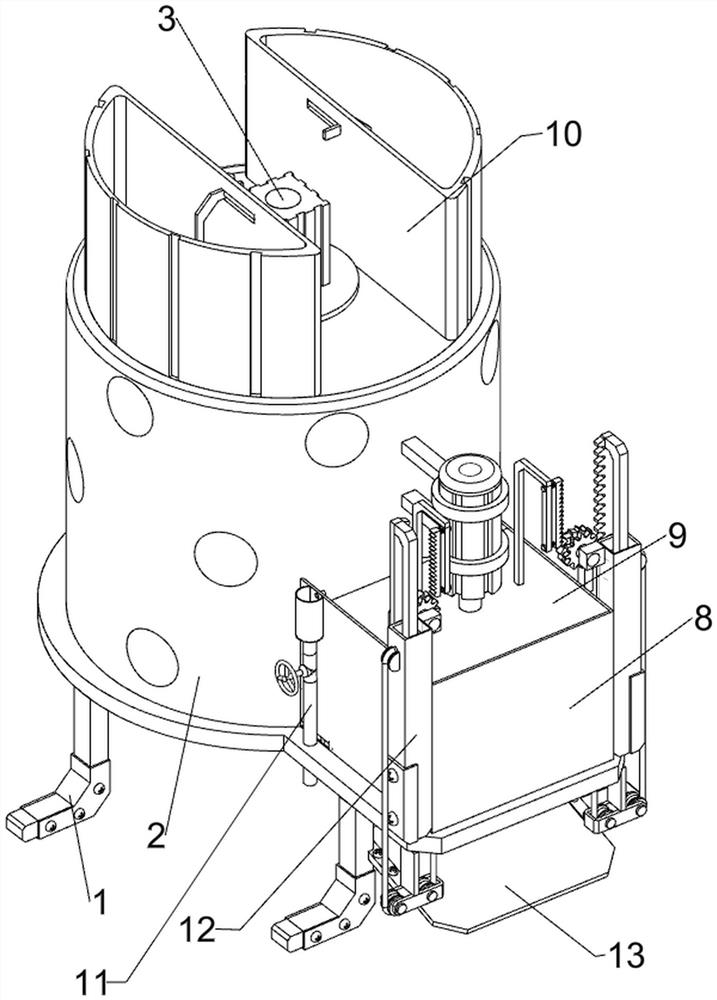
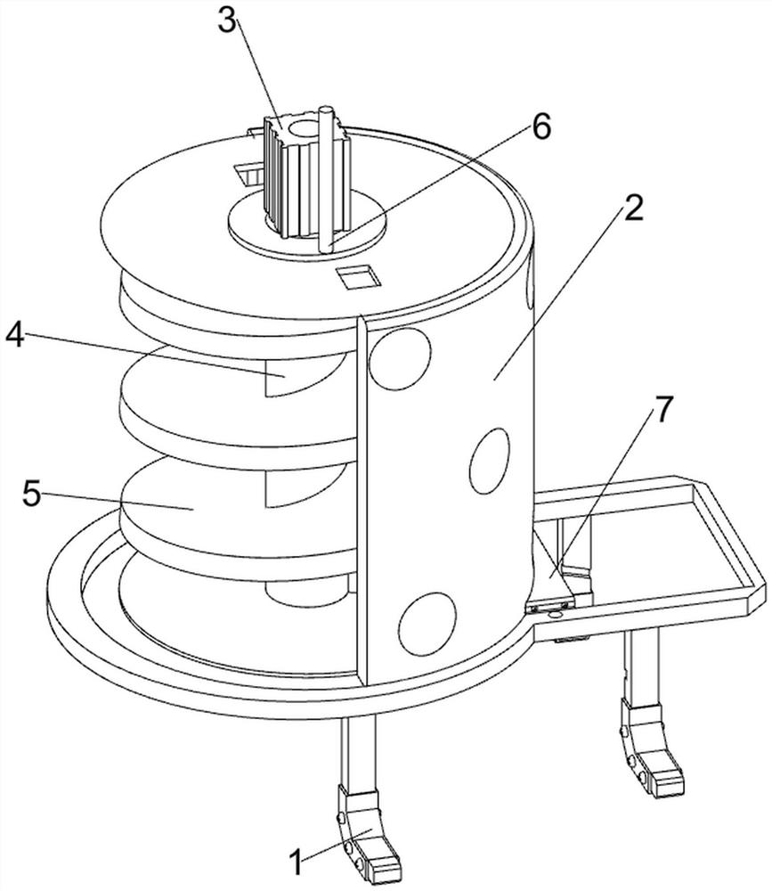
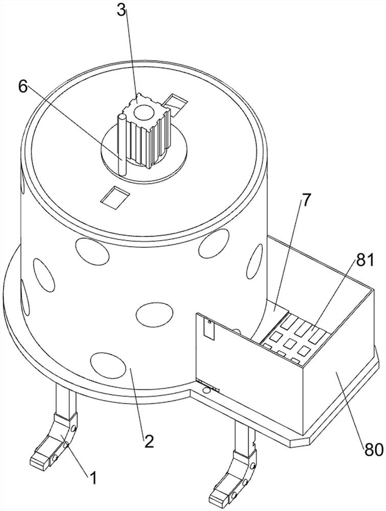
[0071] A kind of aramid fiber film manufacturing equipment, such as figure 1 , figure 2 , image 3 , Figure 4 , Figure 5 and Figure 11 As shown, it includes a support frame 1, a raw material barrel 2, a servo motor 3, a first rotating shaft 4, a screw rod 5, a toggle rod 6, a discharge plate 7, a film mold assembly 8 and a pressing mechanism 9, and the top of the support frame 1 The rear side is provided with a raw material barrel 2, the top of the raw material barrel 2 is provided with a servo motor 3, the lower side of the output shaft of the servo motor 3 is provided with a first rotating shaft 4, the first rotating shaft 4 is provided with a screw rod 5, and the output shaft of the servo motor 3 is provided with a screw rod 5. There is a toggle lever 6, the lower part of the front side of the raw material barrel 2 is provided with a discharge plate 7, the front side of the top of the support frame 1 is provided with a film mold assembly 8, and a pressing mechanism 9 ...

Embodiment 2

[0076] On the basis of Example 1, such as Figure 6 , Figure 7 , Figure 8 , Figure 9 , Figure 10 and Figure 12 As shown, an indirect blanking mechanism 10 is also included, and the indirect blanking mechanism 10 includes a blanking box 100, a second connecting plate 101, a sliding plate 102, a first connecting block 103, a fixed block 104, a limit rod 105 and a first A spring 106, the left and right sides of the raw material barrel 2 are symmetrically provided with a blanking box 100, the inside of the blanking box 100 is slidably connected with a second connecting plate 101, and the bottom of the second connecting plate 101 is provided with a sliding plate 102, and the sliding plates 102 are all It is slidingly connected with the same side of the unloading box 100, and the top of the sliding plate 102 is symmetrically provided with a first connecting block 103, and the left and right sides of the inside of the unloading box 100 are all symmetrically provided with fix...


PUM


Abstract

The invention relates to manufacturing equipment, in particular to aramid film manufacturing equipment. The technical problem to be solved is to provide the aramid film manufacturing equipment which is high in automation degree and low in labor intensity. According to the technical scheme, the aramid film manufacturing equipment comprises a supporting frame and a raw material barrel, wherein the raw material barrel is arranged on one side of the supporting frame; a servo motor arranged at the top of the raw material barrel; a first rotating shaft arranged on one side of an output shaft of the servo motor; a screw rod arranged on the first rotating shaft; a poke rod arranged on the output shaft of the servo motor; a discharging plate arranged on one side of the raw material barrel; and a film mold assembly arranged on one side of the supporting frame. Through the cooperation of an indirect discharging mechanism, the poke rod and the servo motor, the equipment can achieve automatic feeding.

Description

technical field [0001] The invention relates to a manufacturing equipment, in particular to an aramid film manufacturing equipment. Background technique [0002] Para-aramid fiber, that is, poly-p-phenylene terephthalamide fiber, is a quasi-reticular cross-linked near-high polymer with excellent properties such as high strength, high modulus, high temperature resistance, and corrosion resistance. However, due to the high degree of molecular chain orientation and high crystallinity on the surface of aramid fiber, the large steric hindrance of the benzene ring makes it difficult for the hydrogen on the amide group to react with other atoms; in addition, the fiber surface is smooth, the surface area is small, and there is no chemically active group. There is no physical meshing point with the matrix, which greatly affects its application in the field of composite materials. Therefore, it is necessary to make aramid fiber into aramid film to increase the surface area and physica...

Claims


Application Information

Patent Timeline
Patent Type & Authority Applications(China)
IPC IPC(8): B29C43/02B29C43/34B29C43/50B29C43/32B29L7/00
CPCB29C43/02B29C43/34B29C43/50B29C43/32B29L2007/00
Inventor 陈晓东
Owner 江西省恩铂力新材料科技有限公司
Learn More