
Die-cutting machine roller cutter with automatic waste discharging function

A die-cutting machine and self-discharging technology, which is applied in metal processing and other directions, can solve the problems of the roller knife without self-discharging function, low waste discharge rate, and rubber pulling, etc., to achieve the effects of low pressure, improved efficiency, and high efficiency

Pending Publication Date: 2021-02-02
WUJIANG TENGDA PACKING PROD
View PDF14 Cites 0 Cited by
  • Summary
  • Abstract
  • Description
  • Claims
  • Application Information

AI Technical Summary

Problems solved by technology

[0004] The traditional roller knife has no self-discharging function, and the die-cutting machine needs to add an additional waste discharge mechanism, such as the use of thimbles, etc. The waste discharge rate of these methods is low, and it is easy to squeeze to the edge to cause glue pulling and overflow.

Method used


Image

  • Die-cutting machine roller cutter with automatic waste discharging function
  • Die-cutting machine roller cutter with automatic waste discharging function
  • Die-cutting machine roller cutter with automatic waste discharging function

Examples


Embodiment Construction

[0028] In order to describe the technical content, structural features, goals and effects of the present invention in detail, the following examples are given to describe the embodiments in conjunction with the accompanying drawings.

[0029] In describing the present invention, it is to be understood that the terms "central", "longitudinal", "transverse", "front", "rear", "left", "right", "vertical", "horizontal", The orientations or positional relationships indicated by "top", "bottom", "inner", "outer", etc. are based on the orientations or positional relationships shown in the drawings, and are only for the convenience of describing the present invention and simplifying the description, rather than indicating or implying The devices or elements referred to must have a specific orientation, be constructed and operate in a specific orientation, and therefore should not be construed as limiting the scope of the invention.

[0030] The present invention provides a die-cutting ...


PUM


Abstract

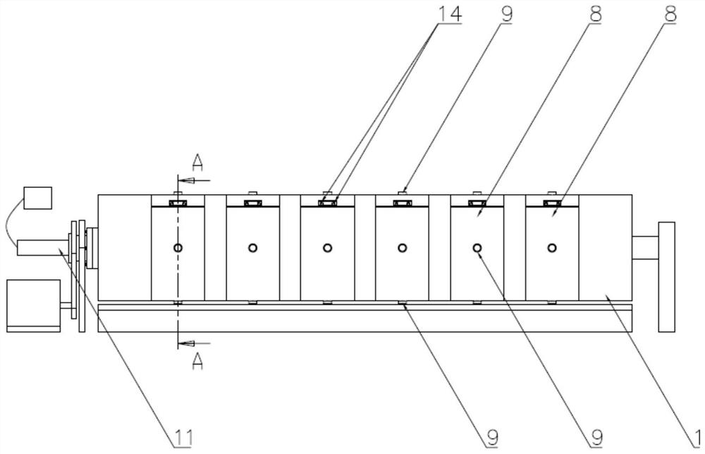
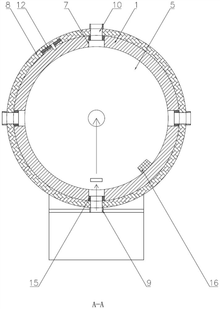
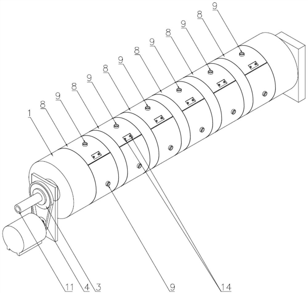
The invention provides a die-cutting machine roller cutter with an automatic waste discharging function. The die-cutting machine roller cutter comprises a roller body and a gear motor driving the roller body to rotate, wherein one end of the roller body is connected with a hollow shaft through a flange, and the hollow shaft is connected with a driven wheel through a spline; the power output end ofthe gear motor is connected with a driving wheel, and the driven wheel is connected with the driving wheel through a chain or a belt; a cavity communicating with the interior of the hollow shaft is formed in the roller body, a plurality of annular grooves are evenly formed in the roller body in the axial direction of the roller body, and waste discharging grooves communicating with the cavity areformed in the annular grooves in the radial direction of the roller body; the annular grooves are detachably connected with a cutter belt, fixing devices are arranged between the cutter belt and theannular grooves, the cutter belt comprises a belt body and a plurality of cutter dies arranged on the belt body, the cutter dies are in a hollow boss shape, and through holes are formed in the positions, corresponding to the cutter dies, of the belt body; the hollow shaft is internally connected with a waste discharging pipe through a bearing, and the waste discharging pipe is connected with an air pump; and the cutting dies, the through holes, the waste discharging grooves, the cavity and the waste discharging pipe form an automatic waste discharging channel. According to the die-cutting machine roller cutter with the automatic waste discharging function, automatic waste discharging can be achieved in the die-cutting machining process.

Description

technical field [0001] The invention relates to the field of optical device processing equipment, in particular to a die-cutting machine roller knife with the function of self-discharging waste. Background technique [0002] Photoelectric display thin film devices mainly include optical films and tapes for photoelectric display. Optical film mainly includes reflective film, diffuser film, prism film, double prism film and integrated (or composite) optical film, etc. Tapes for photoelectric display can be subdivided into adhesive products and insulating products according to their uses: Adhesive tapes used in adhesive products can be divided into single-sided tape and double-sided tape according to the form, and can be divided into two types: base material tape and non-base material tape according to the base material, and base material tape can be divided into PET base material Adhesive tape, non-woven base tape, and foam tape, etc. Photoelectric display thin film devices ...

Claims


Application Information

Patent Timeline
IPC IPC(8): B26D7/18B26F1/44
CPCB26D7/18B26F1/44
Inventor 王建强
Owner WUJIANG TENGDA PACKING PROD
Learn More