Environment-friendly range hood for smart home

A smart home and smoke machine technology, applied in household stoves, household heating, household heating, etc., can solve the problem of reduced gas flow in smokers and achieve the effect of avoiding adhesion

Inactive Publication Date: 2020-12-04
广州国智机电设备有限公司
View PDF0 Cites 1 Cited by
  • Summary
  • Abstract
  • Description
  • Claims
  • Application Information

AI Technical Summary

Problems solved by technology

[0003] Based on the above-mentioned discovery by the present inventors, the existing methods mainly have the following disadvantages, for example: when the oil fume is extracted by the equipment, the oil liquid roasted at high temperature during cooking will be extracted by the equipment in the form of water mist, and the smoke in the smoke will be extracted by the equipment. Some of the oil molecules contained will adhere to the filter screen of the extraction port of the equipment to form a scab layer with the extraction of the equipment. As the thickness of the oil adhesion increases, the gap between the wires of the filter screen gradually becomes smaller, so that the hood Reduced gas flow during extraction

Method used


Image

  • Environment-friendly range hood for smart home
  • Environment-friendly range hood for smart home
  • Environment-friendly range hood for smart home

Examples


Embodiment 1

[0027] as attached figure 1 to attach Figure 5 Shown:

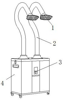
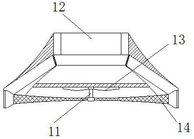
[0028] The present invention provides an environment-friendly smoking machine for smart home use. Its structure includes an extraction head 1, a connecting pipe 2, a control center 3, and an equipment cabin 4. The extraction head 1 is embedded and installed at the end of the connecting pipe 2. The connecting pipe 2 is installed on the upper outer end surface of the equipment cabin 4 by welding, the control center 3 is embedded in the outer end surface of the equipment cabin 4, and the equipment cabin 4 is embedded directly under the extraction head 1; the extraction head 1 includes Connecting rod 11, inlaid opening 12, impeller 13, filter screen mechanism 14, the connecting rod 11 is inlaid and installed in the center of the net mechanism 14, the inlaid opening 12 is embedded and installed directly above the impeller 13, the The impeller 13 is movably mounted on the inner end surface of the extraction head 1 , and the ...

Embodiment 2

[0036] as attached Figure 7 to attach Figure 8 As shown: the storage groove 414 includes a rotating shaft 141, an inlay ring 142, a second embedding block 143, and a balance weight 144. The rotating shaft 141 is embedded and installed directly above the balance weight 144. The second embedding block 143 is closely connected, and the second embedding block 143 is fitted and wrapped on the outer end surface of the inlay ring 142. The balance block 144 is embedded and installed on the second embedding block 143, and the inlay ring 142 The upper end is provided with a limit angle and the inner side is provided with an arc-shaped groove. When the inlaid ring 142 is used to cooperate with the inlaid bead 331 in the support mechanism 133, the effect of inlaid engagement between the two connecting end faces can still be guaranteed. Rotation between devices.

[0037] Wherein, the rotating shaft 141 includes a rubber block 1a, a second ball 1b, a rubber ring 1c, a chute 1d, and a po...


PUM


Abstract

The invention discloses an environment-friendly range hood for smart home. The environment-friendly range hood structurally comprises a sucking head, a communicating pipe, a control center and an equipment cabin; the sucking head is fixedly installed at the tail end of the communicating pipe in an embedded mode, the communicating pipe is installed on the outer end face of the upper side of the equipment cabin in a welded mode, the control center is embedded in the outer side end face of the equipment cabin, and the equipment cabin is embedded under the sucking head. Due to the fact that a converging opening and a supporting mechanism are arranged in a flow guiding opening, in the rotating process of a filter screen mechanism, movable clamping between the converging opening and the supporting mechanism can be formed by embedding a groove formed by the outer contour of the embedding and fixing block and a containing groove, and air can be driven into the containing groove through centrifugal force on the premise that rotation of the filter screen mechanism is not limited, the situation that when the equipment is used in a kitchen, smoke and grease particles adhere to the surface of the sucking head, and consequently the actual air sucking flow of the equipment is affected is avoided.

Description

technical field [0001] The invention belongs to the field of smart home, and more specifically, relates to an environment-friendly smoker for smart home. Background technique [0002] The smart home smoker is a kind of application in the kitchen or the room that has just been decorated. The air in the connecting pipe is extracted through the vacuum extractor in the equipment. The air flow in the connecting pipe forms a strong adsorption force, and the air is absorbed by the adsorption force The dust, oil fume and methane in the air are extracted. [0003] Based on the above-mentioned discovery by the present inventors, the existing methods mainly have the following disadvantages, for example: when the oil fume is extracted by the equipment, the oil liquid roasted at high temperature during cooking will be extracted by the equipment in the form of water mist, and the smoke in the smoke will be extracted by the equipment. Some of the oil molecules contained will adhere to the...

Claims


Application Information

Patent Timeline
Patent Type & Authority Applications(China)
IPC IPC(8): F24C15/20
CPCF24C15/2035
Inventor 张先娣
Owner 广州国智机电设备有限公司
Why Eureka
Try Eureka