Measuring tool and method for measuring angle of rectifying blade with positioning pin

A technology of rectifying blades and positioning pins, applied in measuring devices, mechanical measuring devices, angle/taper measurement, etc., can solve problems such as difficult detection, and achieve the effect of simple structure of the measuring tool and convenient detection

Active Publication Date: 2020-12-04
CHINA HANGFA GUIZHOU LIYANG AVIATION POWER CO LTD
View PDF11 Cites 0 Cited by
  • Summary
  • Abstract
  • Description
  • Claims
  • Application Information

AI Technical Summary

Problems solved by technology

The angle is the key dimension of the part, but the angle dimension is the dimension of the theoretical imaginary intersection line with the surface, and it is not on the part entity, so it is difficult to detect

Method used


Image

  • Measuring tool and method for measuring angle of rectifying blade with positioning pin
  • Measuring tool and method for measuring angle of rectifying blade with positioning pin
  • Measuring tool and method for measuring angle of rectifying blade with positioning pin

Examples


Embodiment Construction

[0026] The present invention will be further described below in conjunction with accompanying drawing and specific embodiment:

[0027] The three-dimensional schematic diagram of measuring instrument structure of the present invention is as figure 2 As shown, it is mainly composed of a base 1, a pressure rod 4, a nut 3, a bolt, a vertical plate 7, a support block 8, a hinged seat 9, a base 10, an angle indicating block 5 and a rotating ring body 6, and the vertical plate 7 is perpendicular to the base 1, the vertical plate 7 has a through hole, the front end of the vertical plate 7 is a base 10, and there is a circle of annular protrusions on the outer circumference of the rear end through hole, and the rotating ring body 6 is sleeved on the annular protrusions, and the rotating ring There is a radial through groove on the body 6, and a through hole on the annular protrusion. The angle indicator block 5 is slidably connected in the through groove and the through hole, and is ...


PUM


Abstract

The invention discloses a measuring tool and method for measuring the angle of a rectifying blade with a positioning pin. The measuring tool is mainly composed of a pedestal, a pressing rod, a nut, abolt, a vertical plate, a supporting block, a hinge seat, a pedestal, an angle indication block, and a rotating ring body. The vertical plate is perpendicular to the upper end surface of the pedestal,the vertical plate is provided with a through hole, and the pedestal is arranged at the front end of the vertical plate. A circle of annular protrusion is arranged on the periphery of the through hole in the rear end in the circumferential direction, the annular protrusion is sleeved with the rotating ring body, a radial through groove is formed in the rotating ring body, a through hole strip isformed in the annular protrusion, and the angle indicating block is slidably connected into the through groove and the through hole strip and connected with a boss on the rectifying blade positioningblock in an inserted mode through a notch in the tail end of the angle indicating block to form an extension structure of the reference surface on the boss. The supporting block is located on the upper end surface of the base, the contour of the upper surface of the supporting block is consistent with the curve shape of the to-be-measured cross section of a blade, one end of a pressing rod is hinged to a hinge base, and the other end of the pressing rod is connected with the bolt in an inserted mode through the notch and locked through the nut. Whether the size of the machined rectifying bladepart is qualified or not can be conveniently judged.

Description

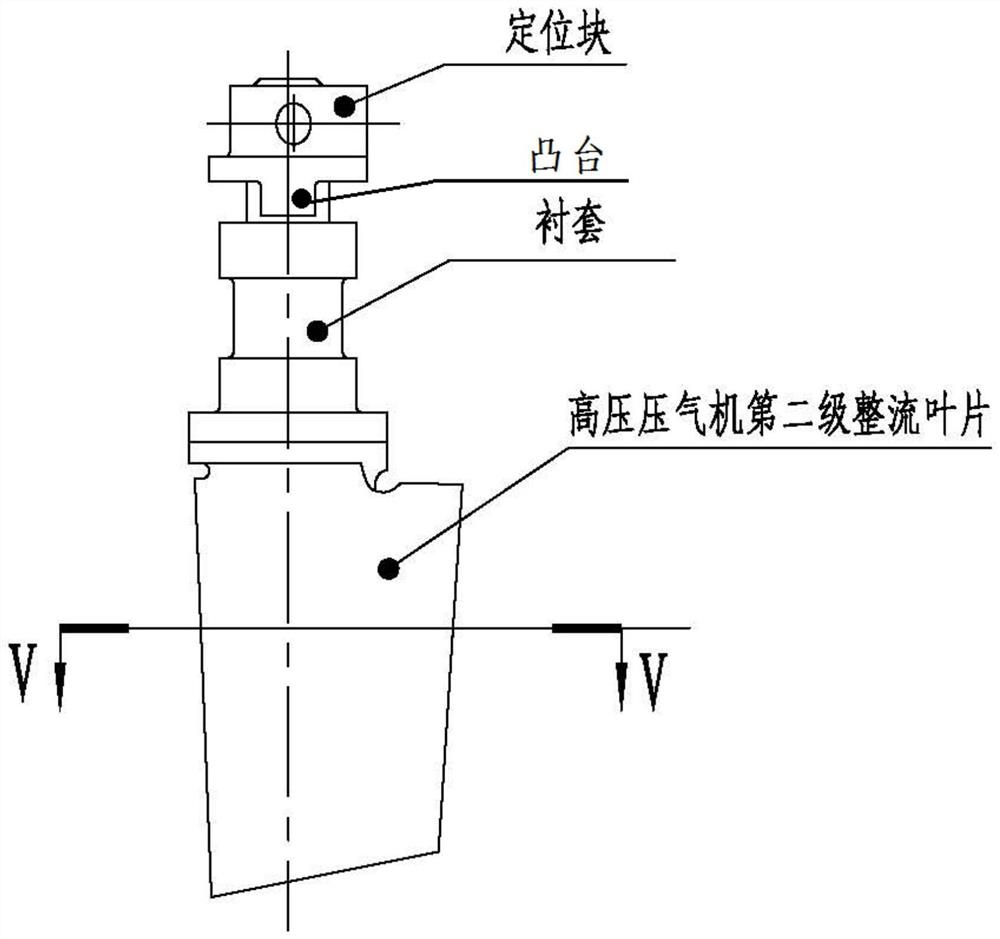
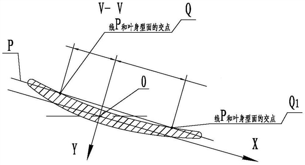
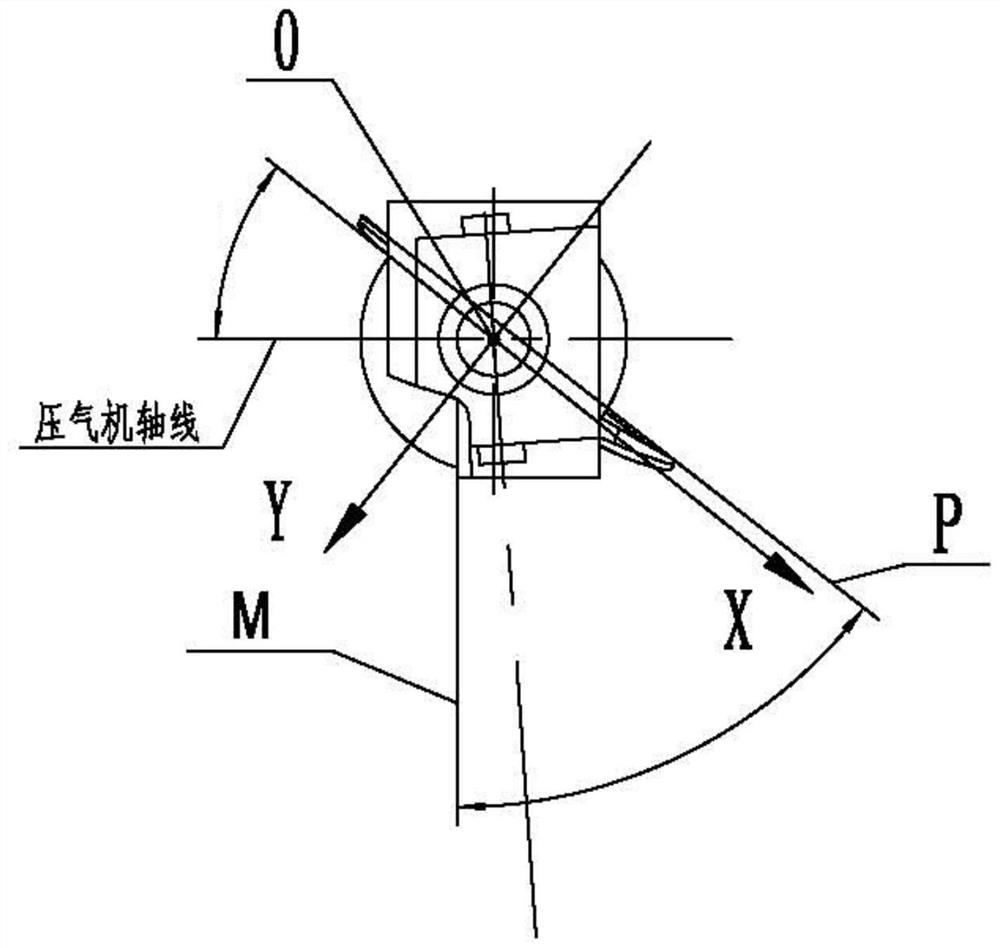
technical field [0001] The invention belongs to the technical field of aero-engine manufacturing, and relates to a processing method for rectifying blades with positioning pins, in particular to a measuring tool and a measuring method for measuring the angle of general rectifying blade parts. Background technique [0002] In aero-engines, straightening blades are a key component in compressors. The straightening blade with positioning pin is a typical part of the compressor straightening blade. like figure 1 , Picture 1-1 and Figure 1-2 As shown, the rectifying blade with positioning pin is mainly composed of the second-stage rectifying blade of the high-pressure compressor, the bushing and the positioning block. The second-stage rectifying blade, the bushing and the positioning block are on the same axis, and the boss Located on the positioning block, there is a datum surface M on the boss of the positioning block, and the positioning pin is plugged into the positioni...

Claims


Application Information

Patent Timeline
Patent Type & Authority Applications(China)
IPC IPC(8): G01B5/24G01B5/00
CPCG01B5/24G01B5/003G01B5/0002G01B5/0004F04D27/001F04D29/563
Inventor 陈强刘承斌罗聪曹莎莎杨新建
Owner CHINA HANGFA GUIZHOU LIYANG AVIATION POWER CO LTD
Why Eureka
Try Eureka