Musical instrument storage box convenient to take and place

A technology for storing boxes and musical instruments, applied in the field of musical instruments

Inactive Publication Date: 2020-12-04
王聪聪
View PDF1 Cites 0 Cited by
  • Summary
  • Abstract
  • Description
  • Claims
  • Application Information

AI Technical Summary

Problems solved by technology

[0004] The present invention provides a musical instrument storage box that is easy to pick and place, which solves the problems in the above-mentioned background technology

Method used


Image

  • Musical instrument storage box convenient to take and place
  • Musical instrument storage box convenient to take and place
  • Musical instrument storage box convenient to take and place

Examples


Embodiment 1

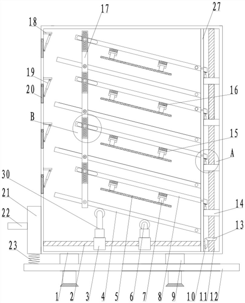
[0023] see Figure 1-5 , a musical instrument storage box that is easy to pick and place, including a storage box 1, one side of the storage box 1 is fixedly connected to a mounting plate 27, and one side of the mounting plate 27 is hingedly connected to a bearing plate 4, and multiple bearing plates 4 are provided. A transmission connecting rod 17 is arranged in the storage box 1 on the side away from the mounting plate 27 of the bearing plate 4, and the transmission connecting rod 17 is connected between the bearing plates 4, and the bearing plate 4 is hingedly connected with the transmission connecting rod 17. One side of the mounting plate 27 above the bearing plate 4 is hingedly connected to the pressure plate 8, and the side of the pressure plate 8 away from the mounting plate 27 is provided with a chute 81, and the transmission link 17 on the side of the chute 81 is provided with an installation groove 173, and slides in the installation groove 173 Connect the installat...

Embodiment 2

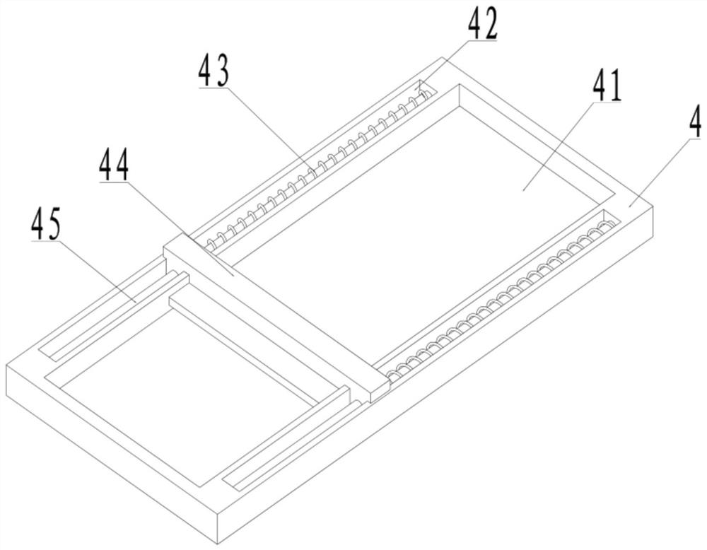
[0029] see Figure 1-5 , the other content of this embodiment is the same as that of Embodiment 1, the difference is that: the carrier plate 4 is provided with a placement groove 41, and the carrier plate 4 on both sides of the placement groove 41 is provided with a sliding groove 42, and the sliding groove 42 is fixedly connected Sliding column 45, a bearing frame 44 is set on the bearing plate 4, the two sides of the bearing frame 44 extend into the sliding groove 42, and are slidably connected with the sliding column 45, and the sliding column 45 on the side of the bearing frame 44 is sleeved with light quality spring43.

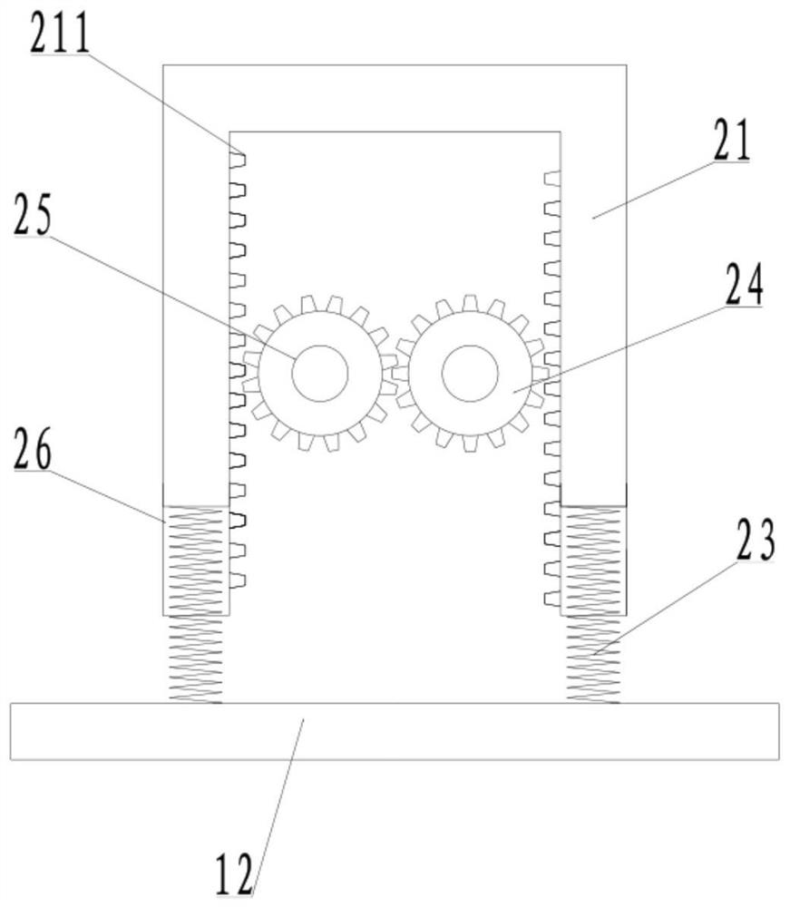
[0030] During the implementation of the present invention, when storing, the operator drives the transmission frame 21 to move down by stepping on the pedal 22, and then drives the first gear 24 to rotate, and the first gear 24 drives the first screw mandrel 2 to rotate, and the first screw The mounting block 3 on the rod 2 drives the support pulley 6 to m...


PUM


Abstract

The invention discloses a musical instrument storage box convenient to take and place, and relates to the technical field of musical instruments; the musical instrument storage box comprises a placement box, a mounting plate is fixedly connected to one side in the placement box, a plurality of bearing plates are hinged to one side of the mounting plate, and a transmission connecting rod is arranged in the placement box on one sides, away from the mounting plate, of the bearing plates. The bearing plates are in transmission connection through the transmission connecting rod, the bearing platesare hinged to the transmission connecting rod, one side of the mounting plate above the bearing plates is hinged to pressing plates, a sliding groove is formed in the side, away from the mounting plate, of each pressing plate, a mounting groove is formed in a part, on one side of each sliding groove, of the transmission connecting rod, and a mounting shaft is slidably connected into each mountinggroove. Telescopic springs are fixedly connected into the mounting grooves in the upper side and the lower side of each mounting shaft, one side of each mounting shaft extends into the sliding grooveof the corresponding pressing plate, each mounting shaft is slidably connected with the corresponding pressing plate through the corresponding sliding groove, and the device is reasonable in structural principle design, convenient to operate and use, convenient to store and take, stable in placement and high in practicability.

Description

technical field [0001] The invention relates to the technical field of musical instruments, in particular to an easy-to-take musical instrument storage box. Background technique [0002] At present, when a musical instrument is packaged or placed, a musical instrument storage box is required, and the existing storage boxes are often unable to protect the musical instrument safely, and often the external collision will cause the musical instrument to be worn or damaged, and the musical instrument cannot be protected. Stable protection does not have the ability to place musical instruments stably, which reduces the use value of the musical instrument placement box. [0003] In the Chinese invention patent document with the publication number CN108492802A, a stable musical instrument storage box is disclosed. The device sets a motor inside the storage box, and drives the rubber pressure plate under the push block under the action of the screw rod to move the musical instrument....

Claims


Application Information

Patent Timeline
Patent Type & Authority Applications(China)
IPC IPC(8): G10G7/00A45C13/02
CPCA45C13/02G10G7/005
Inventor 王聪聪
Owner 王聪聪
Why Eureka
Try Eureka