Al technical title is built by PatSnap Al team. It summarizes the technical point description of the patent document.
A technology for manufacturing equipment and motors, applied in the direction of manufacturing stator/rotor bodies, etc., can solve the problems of time-consuming and laborious, slow press-fitting speed, etc., and achieve the effect of avoiding rigid connection, reasonable structure, and improving press-fitting speed.
Active Publication Date: 2020-12-04
GUIXI HUATAI COPPER IND CO LTD
View PDF12 Cites 3 Cited by
Summary
Abstract
Description
Claims
Application Information
AI Technical Summary
This helps you quickly interpret patents by identifying the three key elements:
Problems solved by technology
Method used
Benefits of technology
Problems solved by technology
[0003] The existing motor rotor manufacturing equipment has a simple structure. When the bearing is pressed on the shaft of the rotor assembly, the rotor assembly is usually fixed on the equipment manually, the bearing is aligned with the shaft of the rotor assembly, and the bearing is moved by a hydraulic or pneumatic expansion rod. Press-fitting on the shaft of the rotor assembly, this method is time-consuming and labor-intensive, and the speed of press-fitting is slow, so this application discloses a manufacturing equipment for motor rotors to meet the needs
Method used
Image
Click on the blue label to locate the original text in one second.
Reading with bidirectional positioning of images and text.
Examples
Embodiment
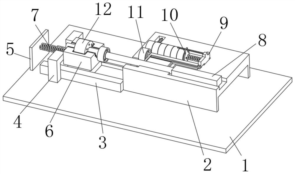
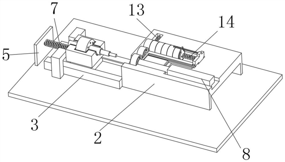
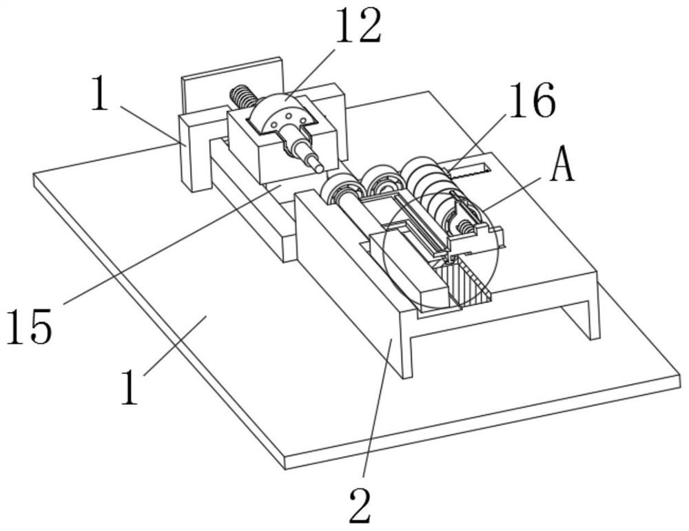
[0028] Example: such as Figure 1-5 The shown manufacturing equipment for a motor rotor includes an operating table 1, which may be any flat plate structure in the prior art, such as a steel plate.
[0029] The top of the console 1 is successively installed with a U-shaped plate 2, a slide rail 3, a pair of L-shaped baffles 4, a fixed plate 5, a U-shaped plate 2, a slide rail 3, a pair of L-shaped baffles 4, a fixed plate 5 and The console 1 is connected by welding in the prior art.
[0030] The top of the U-shaped plate 2 is provided with a cylinder group. The cylinder group includes a cylinder 8 and a push rod. The cylinder group can be any model in the prior art, such as model: sc80x.
[0031] The top of U-shaped plate 2 is provided with connecting rod 17, push plate 9, push block 10, multiple bearings 11, push spring 13, push plate 16, and one end of connecting rod 17 is installed on the push rod, and push plate 9 is connected with One end of the rod 17 is fixedly connec...
PUM
Abstract
The invention discloses manufacturing equipment of a motor rotor, and relates to the technical field of motor rotor manufacturing equipment. The manufacturing equipment comprises an operating table, wherein a U-shaped plate, a sliding rail, a pair of L-shaped baffles and a fixing plate are sequentially arranged at the top part of the operating table, and an air cylinder group is arranged at the top part of the U-shaped plate and comprises an air cylinder and a push rod, a connecting rod, a push plate, a push block, a plurality of bearings, a push spring and a push plate are arranged at the toppart of the U-shaped plate, one end of the connecting rod is installed on the push rod, and a guide rod is installed on the side wall of one side of the push plate. The manufacturing equipment is reasonable in structure, by arranging the connecting rod, the push plate, the push block, a thrust spring, the push spring and the push plate, after each bearing is press-fitted, the bearing placed on aplacement groove is automatically filled and fed, thus semi-automation is achieved, and time and labor are saved; and by arranging a placement block and a compression spring, the bearings do not needto be manually aligned with a rotor assembly shaft, and the press-fitting speed of the bearings is increased.
Description
technical field [0001] The invention relates to the technical field of motor rotor manufacturing equipment, in particular to a motor rotor manufacturing equipment. Background technique [0002] The motor rotor is the rotating part in the motor. The motor is composed of two parts: the rotor and the stator. It is used to realize the conversion device of electric energy and mechanical energy and mechanical energy and electric energy. There are two types of rotor rotation mode and outer rotor rotation mode. The inner rotor rotation mode is that the core body in the middle of the motor is a rotating body, which outputs torque or receives energy. The outer rotor rotation mode uses the outer body of the motor as a rotating body. Different methods facilitate various application in various situations. [0003] The existing motor rotor manufacturing equipment has a simple structure. When the bearing is pressed on the shaft of the rotor assembly, the rotor assembly is usually fixed on...
Claims
Application Information
Patent Timeline
Application Date:The date an application was filed.
Publication Date:The date a patent or application was officially published.
First Publication Date:The earliest publication date of a patent with the same application number.
Issue Date:Publication date of the patent grant document.
PCT Entry Date:The Entry date of PCT National Phase.
Estimated Expiry Date:The statutory expiry date of a patent right according to the Patent Law, and it is the longest term of protection that the patent right can achieve without the termination of the patent right due to other reasons(Term extension factor has been taken into account ).
Invalid Date:Actual expiry date is based on effective date or publication date of legal transaction data of invalid patent.