Hole material removing device for nursing plate of breeding equipment
A device and a technology for placing frames, which are applied in cleaning methods and utensils, cleaning methods using tools, chemical instruments and methods, etc., can solve problems such as low efficiency, large manpower and time consumption
- Summary
- Abstract
- Description
- Claims
- Application Information
AI Technical Summary
Problems solved by technology
Method used
Image

Examples
Embodiment 1
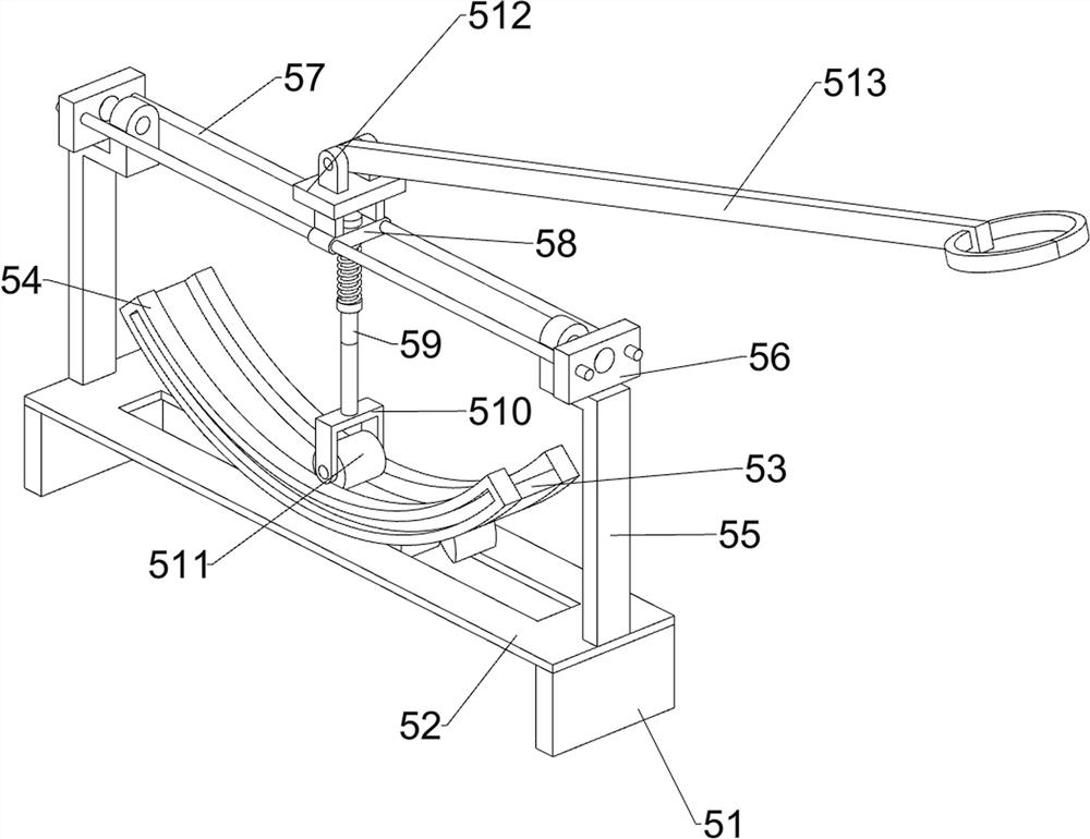
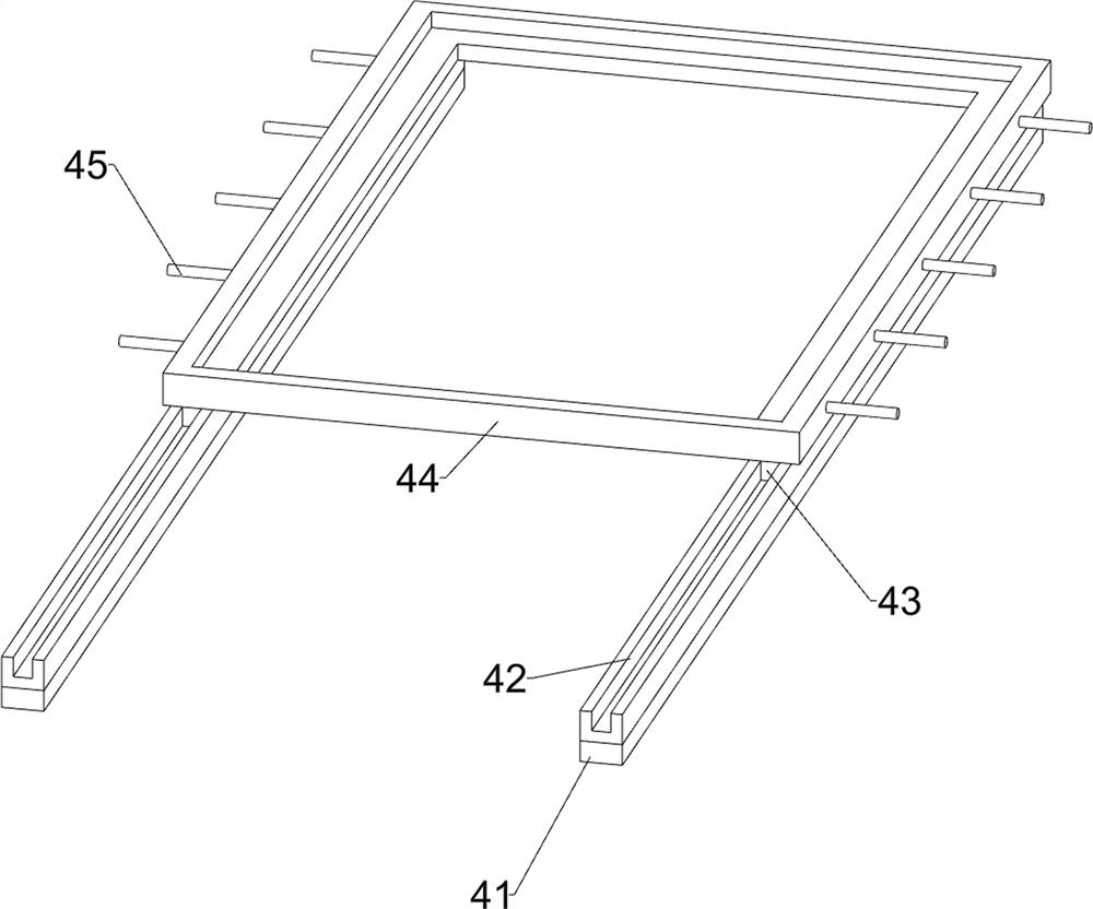
[0024] A breeding equipment nursery plate hole removal device, such as Figure 1-4 As shown, it includes a base 1, a support column 2, a workbench 3, a feeding mechanism 4 and a material removal mechanism 5. There are four support columns 2 on the top of the base 1, and a workbench 3 is fixedly connected between the tops of the support columns 2. , The top of the workbench 3 has a generous groove, the top of the workbench 3 is provided with a feeding mechanism 4, and the workbench 3 is provided with a material removing mechanism 5, and the feeding mechanism 4 is located inside the material removing mechanism 5.
[0025] When people need to use this device, people first place the incubation plate in the feeding mechanism 4, then place the collecting tool on the base 1, and align the collecting tool with the large square groove on the workbench 3, and then push it forward. The material mechanism 4 moves to the left, and then drives the protection plate to move to the left. When ...
Embodiment 2
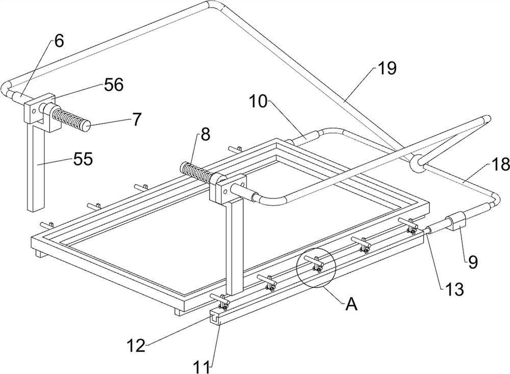
[0031]On the basis of Example 1, such as Figure 4-6 As shown, it also includes a first hydraulic cylinder 6, a first piston 7, a first elastic member 8, a cylinder liner 9, a second hydraulic cylinder 10, a second slide rail 11, a second slider 12, a second piston 13, Sector block 14, connecting shaft 15, toggle lever 16, second elastic member 17, thin conduit 18 and thick conduit 19, the middle part of fixed block 56 is provided with the first hydraulic cylinder 6, and the first hydraulic cylinder 6 inward side Both are provided with a first piston 7 in a sliding manner, and a first elastic member 8 is connected between the first piston 7 and the L-shaped block 55. The first elastic member 8 is a compression spring, and the right side of the top of the workbench 3 is symmetrical front and rear A cylinder liner 9 is provided, and a second hydraulic cylinder 10 is arranged inside the cylinder liner 9. The top of the workbench 3 is symmetrically provided with a second slide rai...
PUM
 Abstract
Description
Claims
Application Information
 - R&D
- Intellectual Property
- Life Sciences
- Materials
- Tech Scout
- Unparalleled Data Quality
- Higher Quality Content
- 60% Fewer Hallucinations
Browse by: Latest US Patents, China's latest patents, Technical Efficacy Thesaurus, Application Domain, Technology Topic, Popular Technical Reports.
© 2025 PatSnap. All rights reserved.Legal|Privacy policy|Modern Slavery Act Transparency Statement|Sitemap|About US| Contact US: help@patsnap.com