Bicycle carrying frame forming machine

A technology for forming machines and bicycles, applied to bicycle accessories, feeding devices, manufacturing tools, etc., can solve the problems of complex operation and low efficiency, and achieve the effect of reducing the difficulty of operation and improving work efficiency.

Active Publication Date: 2020-12-08
朱明昌
View PDF8 Cites 1 Cited by
  • Summary
  • Abstract
  • Description
  • Claims
  • Application Information

AI Technical Summary

Problems solved by technology

[0005] In order to overcome the disadvantages that the bending tool needs to be operated with one hand and the iron frame of the loading frame is picked up with the other hand, the present invention is complicated to operate, and each side needs to be bent once, resulting in low efficiency. The technical problem to be solved by the present invention is to provide a A bicycle loading frame forming machine with simple operation, high efficiency, and capable of bending and forming the iron frame of the loading frame at one time

Method used


Image

  • Bicycle carrying frame forming machine
  • Bicycle carrying frame forming machine
  • Bicycle carrying frame forming machine

Examples


Embodiment 1

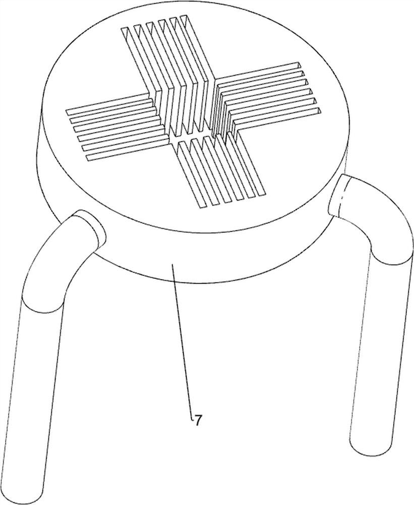
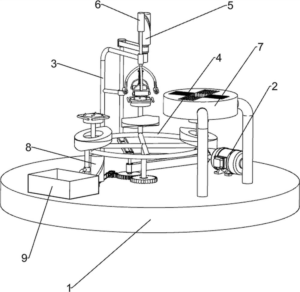
[0027] A bicycle loading frame forming machine, such as Figure 1-4 and Figure 7 As shown, it includes a base plate 1, a motor 2, a long rod 3, a rotating mechanism 4, a pressing mechanism 5, a bending mechanism 6 and a blanking block 7. The motor 2 is installed on the right side of the top of the base plate 1, and the rear of the top of the base plate 1 A long rod 3 is installed on the side, a rotating mechanism 4 is connected in the middle of the top of the bottom plate 1, a bending mechanism 6 is installed on the long rod 3, a pressing mechanism 5 is connected between the bending mechanism 6 and the rotating mechanism 4, and the bending mechanism 6 is located in the Above the rotating mechanism 4, a blanking block 7 is connected to the top front side of the bottom plate 1.

[0028] The rotating mechanism 4 includes a first sleeve 41, a bevel gear set 42, a first rotating shaft 43, a second sleeve 44, a first belt device 45, a missing gear 46, a first spur gear 47, a turnt...

Embodiment 2

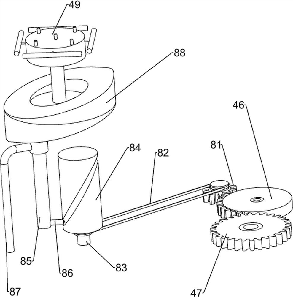
[0033] On the basis of Embodiment 1, such as figure 1 and Figure 5-6 As shown, the ejection mechanism 8 is also included, and the ejection mechanism 8 includes the second spur gear 81, the fourth belt device 82, the fourth rotating shaft 83, the second roller 84, the ejector column 85, the second guide column 86, the Four sets of columns 87 and push blocks 88, the middle of the top of the base plate 1 is connected with the second spur gear 81 in a rotational manner, the second spur gear 81 meshes with the missing gear 46, and the left side of the top of the base plate 1 is connected with the fourth set of columns 87 and the second spur gear. Four rotating shafts 83, the fourth sleeve column 87 is fixedly connected with the base plate 1, the fourth rotating shaft 83 is connected with the base plate 1 in a rotational manner, a fourth belt device 82 is connected between the fourth rotating shaft 83 and the second spur gear 81, and the fourth rotating shaft 83 The top is fixedly...


PUM


Abstract

The invention relates to a forming machine, in particular to a bicycle carrying frame forming machine. According to the technical purposes of the bicycle carrying frame forming machine, it is to provide the bicycle carrying frame forming machine which is simple to operate, high in efficiency and capable of bending and forming a carrying frame iron stand at a time. In order to achieve the technicalpurposes, the bicycle carrying frame forming machine is provided and comprises a bottom plate, a long rod, a rotating mechanism, a pressing bending mechanism, a press-down mechanism and a dischargingblock, wherein one side of the top of the bottom plate is connected with an electromotor; the long rod is connected to the bottom plate; the rotating mechanism is installed in the middle of the top of the bottom plate; the pressing bending mechanism is installed on the long rod; the press-down mechanism is connected between the pressing bending mechanism and the rotating mechanism; and the discharging block is connected to the side, close to the electromotor, of the top of the bottom plate. According to the bicycle carrying frame forming machine, through cooperative work of the rotating mechanism, the press-down mechanism and the pressing bending mechanism, the continuity of the forming work of the carrying frame iron stand can be guaranteed, and therefore automatic forming of the carrying frame iron stand is achieved.

Description

technical field [0001] The invention relates to a molding machine, in particular to a bicycle loading frame molding machine. Background technique [0002] The bicycle carrying frame is made of plastic or iron wire, and is installed on the handlebar. The bicycle carrying frame is installed at the front wheel of the bicycle to bring great convenience to the cyclist for shopping. Its application is becoming more and more popular. The mouth of the frame body is mostly rectangular, and it is parallel to the flat tube of the handlebar, so its width is mostly more than 30 centimeters. [0003] At present, when forming a loading frame made of iron wire, it is necessary to bend each side welded into a cross frame with a bending tool. When bending the bending tool, one hand needs to operate the bending tool, and the other hand takes The object frame is an iron frame, and the object frame is placed on the bending tool for bending. The operation is complicated, and each side needs to b...

Claims


Application Information

Patent Timeline
IPC IPC(8): B21D7/022B21D43/00B21D43/20B21D45/04B21D53/86
CPCB21D7/022B21D43/003B21D45/04B21D43/20B21D53/86
Inventor 朱明昌
Owner 朱明昌
Why Eureka
Try Eureka