Magnetic chip removal machine

A chip removal machine and magnetic technology, applied in metal processing machinery parts, maintenance and safety accessories, metal processing equipment, etc., can solve the problems of incomplete chip removal, liquid corrosion equipment and environmental pollution around the equipment, and achieve the effect of thorough chip removal

Pending Publication Date: 2020-12-08
NANTONG GUOSHENG PRECISION MACHINERY
View PDF0 Cites 1 Cited by
  • Summary
  • Abstract
  • Description
  • Claims
  • Application Information

AI Technical Summary

Problems solved by technology

[0005] The purpose of the present invention is to solve the problem that the conventional magnetic chip removal machine is placed in the liquid to attract and remove chips, which causes the liquid to corrode the equipment, easily pollute the surrounding environment, and the problem of incomplete chip removal. The proposed magnetic chip removal machine

Method used


Image

  • Magnetic chip removal machine
  • Magnetic chip removal machine
  • Magnetic chip removal machine

Examples


Embodiment 1

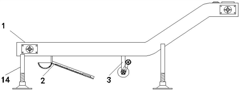
[0030] see figure 1 , a magnetic chip removal machine, including a permanent magnet chip removal machine body 1, a conveyor belt and a permanent magnet are arranged on the permanent magnet chip removal machine body 1, and a water pulse lifting part is arranged on the lower end surface of the permanent magnet chip removal machine body 1 near the end 2 and the water wheel part 3 located on the side of the water pulse lifting part 2 and distributed in the direction of the conveyor belt. The lower end surface of the permanent magnet chip removal machine body 1 is provided with four spiral telescopic legs 14. The spiral telescopic legs 14 It plays the role of supporting and adjusting the height. The water pulse lifting part 2 replaces the permanent magnet chip removal machine body 1 and is in contact with the liquid. The water wheel part 3 pushes the liquid through rotation to generate wave-like water impact, and the wave-like water impact improves the water pulse. The bit part 2 g...

Embodiment 2

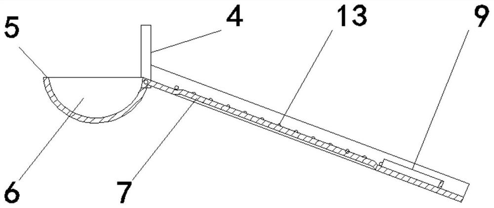
[0032] see Figure 1-3 The water pulse lifting part 2 is composed of two suspension rods 4 fixedly arranged on the top and bottom of the permanent magnet chip removal machine body 1 and symmetrically distributed, and a semicircle body 5 with a rectangular upper end surface. The upper end surface of the semicircle body 5 is provided with a semicircle The water storage tank 6, the side of the outer wall of the semicircle body 5 close to the upper end surface and the opposite side walls of the two suspension rods 4 are hinged near the bottom, the opening direction of the semicircle body 5 is upward and its side close to the two suspension rods 4 is bent There is a lifting plate 7 away from the lower end surface of the semicircular body 5 and the permanent magnet chip removal machine body 1. On the lifting plate 7, two sides close to the suspension rod 4 are bent upwards to have a right-angled water filter coaming 8. The lifting plate The upper end surface of 7 is welded with a fi...

Embodiment 3

[0034] see figure 2 , Figure 4 and Figure 5 , the middle part of the upper end surface of the lifting plate 7 is in the shape of an inverted V-shaped protrusion relatively close to the two sides of the two suspension rods 4, and the inner side walls of the two right-angled water filter enclosures 8 are provided with a uniform surface close to the upper end surface of the lifting plate 7. Distributed water holes 13, the upper end surface of the lifting plate 7 is in the shape of an isosceles trapezoid and the small end is close to the semicircular body 5. After the liquid mixed with iron filings enters the lifting plate 7, the liquid is in a V-shaped convex shape and passes through the water. Under the action of hole 13, rapid drainage and filtration are realized.

[0035] Working principle: When in use, place the four spiral telescopic outriggers 14 at the front end of the permanent magnet chip removal machine body 1 around the liquid tank containing iron filings, and adj...


PUM


Abstract

The invention discloses a magnetic chip removal machine. The magnetic chip removal machine comprises a permanent magnet chip removal machine body, wherein a conveying belt and a permanent magnet are arranged on the permanent magnet chip removal machine body; a water pulse lifting part and a water wheel part are arranged on the lower end surface, close to the end part, of the permanent magnet chipremoval machine body; and the water wheel part is located on one side of the water pulse lifting part and is distributed in the arrangement direction of the conveying belt. According to the magnetic chip removal machine, the water pulse lifting part and the water wheel part are arranged on the lower end surface of the permanent magnet chip removal machine body, the water pulse lifting part is formed by hinging a suspension rod and a semicircular body, a semicircular water storage tank is formed in the upper end surface of the semicircular body, a lifting plate which is obliquely distributed isbent on one side of the semicircular body, one end of the lifting plate is put in liquid, an opening of the semicircular water storage tank faces upwards, the water wheel part rotates to generate water flow pulses, iron chips in flowing water enter the lifting plate, meanwhile, the water flow is pushed into the semicircular water storage tank, the semicircular water storage tank is overturned after being fully loaded with water, the iron chips are driven to ascend to be close to the permanent magnet chip removal machine body, so that the iron chips are adsorbed, and the iron chips do not needto be in direct contact with the liquid.

Description

technical field [0001] The invention relates to the technical field of precision machine tool processing chip removal, in particular to a magnetic chip removal machine. Background technique [0002] When precision machine tools process metal, a large amount of iron filings will be produced. There are many types of iron filings, such as granular, powdery, and iron filings with a length of ≤150 mm. Such iron filings usually follow the cutting fluid into the cutting fluid. In the filter tank, in order to avoid the damage of iron filings to precision machine tools, a magnetic chip removal machine is usually used for chip removal. [0003] At present, the commonly used magnetic chip conveyor is composed of a shell with two-stage corner structure, a conveyor belt inside and a permanent magnet inside the front end. When in use, the front end is usually placed in the liquid, the conveyor belt is running, and the permanent magnet will Iron chips are adsorbed on the conveyor belt, an...

Claims


Application Information

Patent Timeline
Patent Type & Authority Applications(China)
IPC IPC(8): B23Q11/00
CPCB23Q11/0042
Inventor 卫保国姚菊红
Owner NANTONG GUOSHENG PRECISION MACHINERY
Why Eureka
Try Eureka