Offline pneumatic clamping tool
An off-line, clamping technology, applied in the direction of manufacturing tools, workpiece clamping devices, etc., can solve the problems of trachea pinching, pinching by related action mechanisms, and melting, etc., to avoid potential safety hazards, reliable fixation, and simple operation. Effect
- Summary
- Abstract
- Description
- Claims
- Application Information
AI Technical Summary
Problems solved by technology
Method used
Image
Examples
Embodiment 1
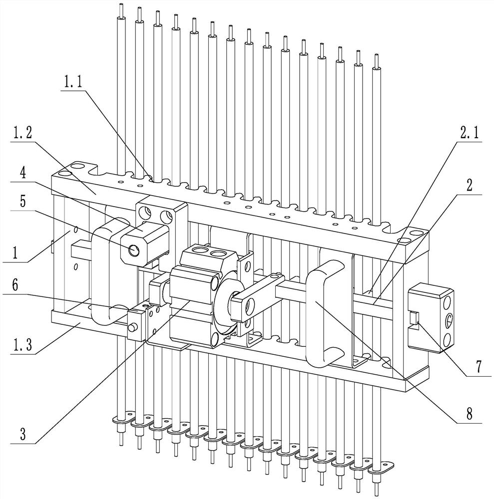
[0025] Such as figure 1 As shown, an off-line pneumatic clamping tool includes a support frame 1, a moving rod 2, a clamping cylinder 3, an inflatable block 4, a first one-way valve 5, a three-way valve 6 and a telescopic spring 7, and the moving rod 2 and The support frame 1 is slidingly connected, one end of the telescopic spring 7 is connected to the support frame 1, the other end of the telescopic spring 7 is connected to the moving rod 2, the clamping cylinder 3 is fixed on the supporting frame 1, and the telescopic rod of the clamping cylinder 3 is connected to the moving rod 2 connection, the inflatable block 4 communicates with the three-way valve 6, the first one-way valve 5 is set in the inflatable block 4, the clamping cylinder 3 communicates with the three-way valve 6; the support frame 1 includes an upper cross bar 1.2 and a lower cross bar 1.3 , The upper cross bar 1.2 and the lower cross bar 1.3 are respectively provided with a row of positioning grooves 1.1, an...
Embodiment 2
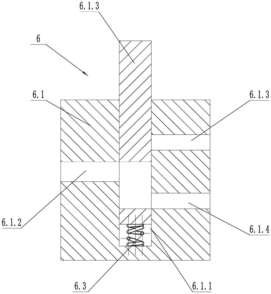
[0028] Such as figure 2As shown, on the basis of Embodiment 1, the three-way valve 6 is a manual three-way valve 6, and the three-way valve 6 includes a fixed block 6.1, a sliding block 6.2 and a second spring 6.3, and the fixed block 6.1 is provided with a chute 6.1. 1. The sliding block 6.2 is adapted to the chute 6.1.1. The sliding block 6.2 is set in the chute 6.1.1 and is slidably connected with the fixed block 6.1. One end of the sliding block 6.2 extends out of the chute 6.1.1, and the second spring 6.3 One end is connected with the fixed block 6.1, the other end of the second spring 6.3 is connected with the sliding block 6.2, the fixed block 6.1 is provided with the first air port 6.1.2, the second air port 6.1.3 and the third air port 6.1.4, the sliding block 6.2 There is a linkage groove 6.2.1 on it, and the linkage groove 6.2.1 communicates with the first air port 6.1.2 and the second air port 6.1.3 or communicates with the first air port 6.1.2 and the third air p...
Embodiment 3
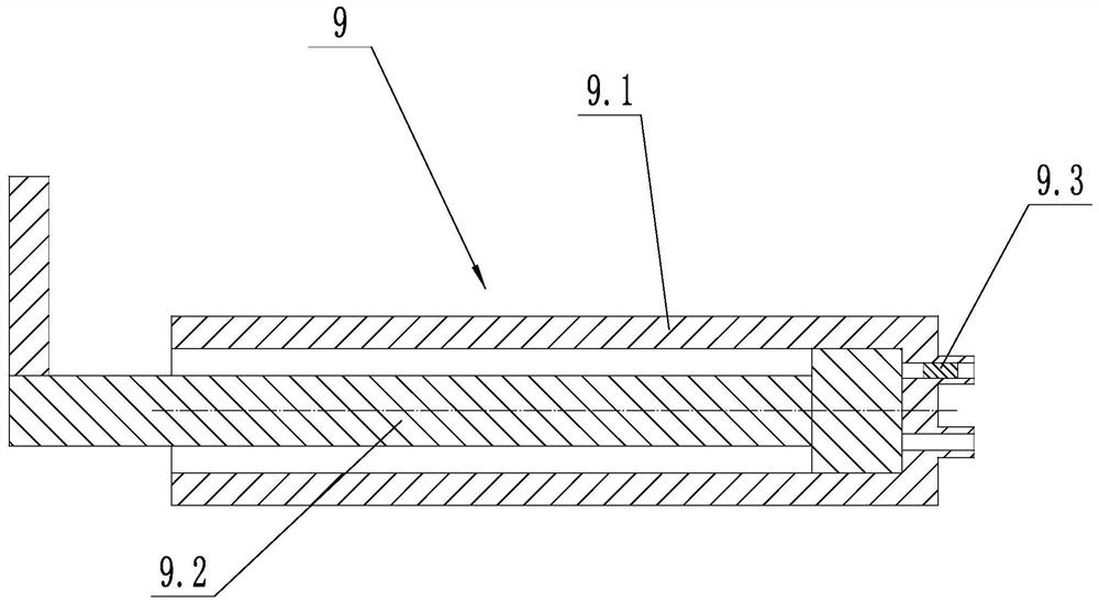
[0030] Such as image 3 As shown, on the basis of Embodiment 1, an inflator 9 is also included. The inflator 9 includes an air cylinder 9.1, a piston rod 9.2 and a second one-way valve 9.3. The air outlet of 9.1 communicates with the inflatable block 4, and the second one-way valve 9.3 is arranged on the air inlet of the air cylinder 9.1. The air cylinder 9.1 is arranged laterally on the support frame 1, and the sliding direction of the piston rod 9.2 is the same as the telescopic direction of the clamping cylinder 3. The piston rod 9.2 is provided with an operating pad, and the inner diameter of the air cylinder 9.1 is smaller than that of the clamping cylinder 3 .
[0031] The inflation device 9 can inflate the inflation block 4, and the clamping tool does not need an additional inflation gas source, which is more convenient to operate. Pushing the piston rod 9.2 can realize the inflation function during use. The arrangement of the gas cylinder 9.1 can make the structure ...
PUM
 Abstract
Description
Claims
Application Information
 - R&D
- Intellectual Property
- Life Sciences
- Materials
- Tech Scout
- Unparalleled Data Quality
- Higher Quality Content
- 60% Fewer Hallucinations
Browse by: Latest US Patents, China's latest patents, Technical Efficacy Thesaurus, Application Domain, Technology Topic, Popular Technical Reports.
© 2025 PatSnap. All rights reserved.Legal|Privacy policy|Modern Slavery Act Transparency Statement|Sitemap|About US| Contact US: help@patsnap.com


