Surface water pollution treatment equipment

A water pollution and equipment technology, applied in the field of water pollution treatment, can solve the problems of slow sludge dewatering, increase the bearing capacity of the external blade of the screw, slow down the rotation speed of the screw, etc. The effect of rotation speed

Inactive Publication Date: 2020-12-08
王云云
View PDF0 Cites 0 Cited by
  • Summary
  • Abstract
  • Description
  • Claims
  • Application Information

AI Technical Summary

Problems solved by technology

[0002] Surface water is an important source of water for human life, and agricultural water is a part of surface water. Since a large amount of agricultural chemicals are used in agricultural water and mixed with sludge, in order to speed up the treatment and purification of agricultural water, the process of purifying agricultural water is first Use a sludge dehydrator to separate water and sludge; when using a sludge dewaterer in the prior art, because the sludge is sticky and m...

Method used


Image

  • Surface water pollution treatment equipment
  • Surface water pollution treatment equipment
  • Surface water pollution treatment equipment

Examples


Embodiment 1

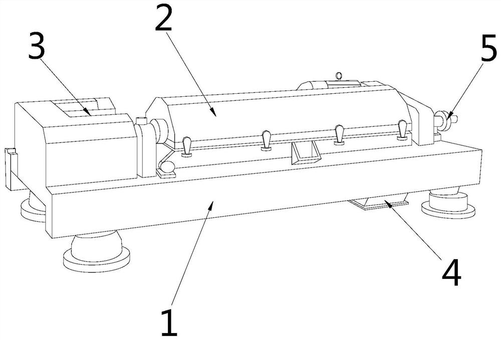
[0025] as attached figure 1 to attach Figure 5 Shown:

[0026] The invention provides a surface water pollution treatment equipment, the structure of which includes a base 1, a drum 2, a water inlet 3, a sludge outlet 4, and a water outlet 5, the drum 2 is set on the top of the base 1, and the water inlet 3 is located on the top of the drum 2 on the left side, the sludge outlet 4 is located on the right side of the bottom of the base 1, and the water outlet 5 is connected to the right end of the drum 2.

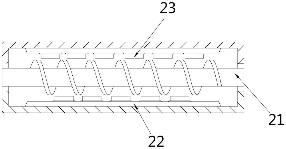
[0027] The drum 2 includes a screw rod 21, a support seat 22, and a block 23, the screw rod 21 is arranged in the middle of the drum 2, the support seat 22 is fixed on the inner wall of the drum 2, and the block 23 is installed on the support seat 22 surface.

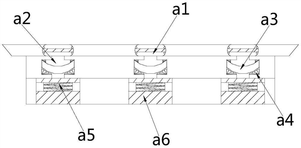
[0028] Wherein, the block 23 includes an opening a1, a water tank a2, an impact plate a3, a bottom block a4, a spring a5, and a clearing block a6, the opening a1 runs through the top of the block 23, the water tank...

Embodiment 2

[0034] as attached Figure 6 to attach Figure 7 Shown:

[0035] Wherein, the impact plate a3 includes a top groove r1, a water inlet groove r2, a push rod r3, an extrusion block r4, a water storage chamber r5, and a bottom plate r6. The top groove r1 runs through the top of the impact plate a3, and the water inlet groove r2 respectively Located on the inner walls of both sides of the impact plate a3, the push rod r3 is arranged on both sides of the inner wall of the impact plate a3, the extrusion block r4 is movably matched with the push rod r3, the water accumulation chamber r5 is located inside the impact plate a3, and the bottom plate r6 is fixed on the bottom surface of the impact plate a3, and the surface of the extrusion block r4 close to the middle of the impact plate a3 is an irregular surface, which is beneficial to increase the contact area with the sewage, accelerate the extrusion of the sewage, and increase the impact force of the sewage.

[0036] Wherein, the b...


PUM


Abstract

The invention discloses surface water pollution treatment equipment which structurally comprises a base, a roller, a water inlet, a sludge outlet and a water outlet, sludge is contained in sewage andhas viscosity, a mucous membrane is easily formed between a screw rod and the inner wall of the roller, and a clearing block in a clamping block is moved out of the bottom of the clamping block through the thrust of the sewage; the fan blades in the clearing block rotate under the thrust of water flow, and the blades on the surfaces of the fan blades pierce mucous membranes of the screw rod and the inner wall of the roller so that impurities blocked by the mucous membranes are accelerated to pass through, the mucous membranes are reduced, the rotating speed of the screw rod is increased, and mud-water separation of sewage is accelerated; when the fan blades clears the mucous membranes, sludge and impurities in sewage are easily attached to the surfaces of the fan blades, the sewage is pressurized for multiple times through the impact plate, the impact force of the sewage is increased to impact the fan blades, falling of the sludge and the impurities on the surfaces of the fan blades isfacilitated, the gravity of the fan blades is reduced, the rotating speed of the fan blades is increased, and mucous membranes are accelerated to be pierced.

Description

technical field [0001] The invention belongs to the field of water pollution treatment, and more specifically relates to surface water pollution treatment equipment. Background technique [0002] Surface water is an important source of water for human life, and agricultural water is a part of surface water. Since a large amount of agricultural chemicals are used in agricultural water and mixed with sludge, in order to speed up the treatment and purification of agricultural water, the process of purifying agricultural water is first Use a sludge dehydrator to separate water and sludge; when using a sludge dewaterer in the prior art, because the sludge is sticky and mixed with agricultural water, when the screw inside the dehydrator rotates at a high speed, the screw will It is easy to form a water film with the inner wall of the drum, resulting in the impurity of small crops contained in the agricultural water being blocked by the water film, and the impurities are attached t...

Claims


Application Information

Patent Timeline
IPC IPC(8): C02F11/121
CPCC02F11/121
Inventor 王云云
Owner 王云云
Why Eureka
Try Eureka