
Rainproof electric power iron tower capable of avoiding rainwater conduction and electric shock

A power iron tower and conduction technology, applied in the field of power iron towers, can solve the problems of unfavorable electric shock protection of power iron towers, easy attachment to the connection between the upper part of the hanging insulator and the fixed bracket, lack of rain and snow protection structure, etc., to achieve convenient clamping , avoid conduction, avoid the effect of connecting conduction

Inactive Publication Date: 2020-12-08
奚梦靖
View PDF7 Cites 1 Cited by
  • Summary
  • Abstract
  • Description
  • Claims
  • Application Information

AI Technical Summary

Problems solved by technology

[0004] The object of the present invention is to provide a kind of rain-proof electric power tower that avoids rainwater conduction electric shock, to solve the existing electric power tower on the market that the above-mentioned background technology proposes, after erecting cable, generally adopt suspension insulator to fix cable, but There is no corresponding rain and snow-proof structure between the upper part of the suspension insulator and the fixed brackets on both sides of the power tower. The formation of conductors is not conducive to the protection of electric towers against electric shock

Method used


Image

  • Rainproof electric power iron tower capable of avoiding rainwater conduction and electric shock
  • Rainproof electric power iron tower capable of avoiding rainwater conduction and electric shock
  • Rainproof electric power iron tower capable of avoiding rainwater conduction and electric shock

Examples


Embodiment Construction

[0024] Based on the embodiments of the present invention, all other embodiments obtained by persons of ordinary skill in the art without making creative efforts belong to the protection scope of the present invention.

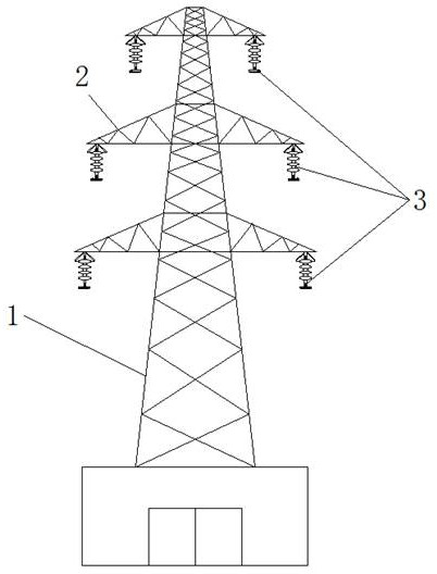
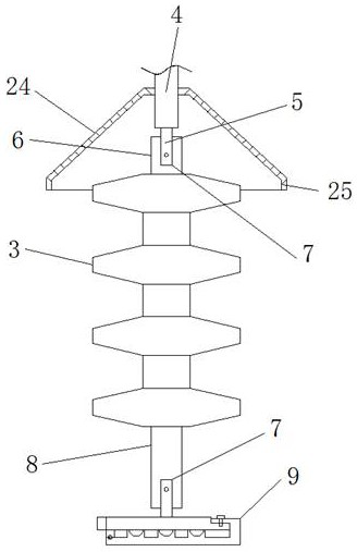
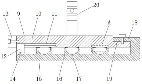
[0025] see Figure 1-6 , the present invention provides a technical solution: a rain-proof power tower for avoiding rainwater conduction and electric shock, comprising a power tower body 1, a fixed bracket 2, a suspension insulator 3, an upper fixed column 4, a connector 5, a bushing 6, Fixing groove 7, lower fixing column 8, clamping structure 9, upper splint 10, adjusting groove 11, adjusting block 12, blocking block 13, hinge 14, lower splint 15, clamping block 16, cable groove 17, fastening block 18. Fastening groove 19, installation head 20, deflection groove 21, reset shaft 22, baffle 23, rainproof structure 24 and baffle ring 25, fixed brackets are provided on both sides of the upper part of the power tower body 1 2, and the lower side of the outer end ...


PUM


Abstract

The invention discloses a rainproof electric power iron tower capable of avoiding rainwater conduction and electric shock. The rainproof electric power iron tower comprises an electric power iron tower body, fixing supports, suspension insulators, hinges and reset rotating shafts, wherein the fixing supports are correspondingly arranged on the two sides of the upper portion of the electric power iron tower body, the suspension insulators are arranged on the lower sides of the outer ends of the fixing supports, sleeve pipes are arranged at the upper ends of the suspension insulators, fixing grooves are formed in the upper end faces of the sleeve pipes, the fixing grooves are fixedly connected with connectors through screws, and a mounting head is located in the middle of the upper end faceof a wire clamping structure. According to the rainproof electric power iron tower capable of avoiding rainwater conduction and electric shock, by improving the structure of the connecting position ofan existing electric power iron tower and the suspension insulators, the problem that rainwater or snow is attached to the connecting positions of the upper portions of the suspension insulators andthe fixing supports in rainy and snowy days is effectively solved, communication and electric conduction between a cable and the electric power iron tower are avoided, and the problem that ground personnel is in accidental contact with the electric power iron tower body to be electrified and put in is solved.

Description

technical field [0001] The invention relates to the technical field of electric power towers, in particular to a rainproof electric power tower that prevents rainwater conduction and electric shock. Background technique [0002] A power tower is a steel tower-shaped building for power transmission. Its main structure is a tower-shaped truss structure that is lapped by various angle steel rods and connecting steel plates through bolts. One or more layers of fixed brackets will be erected on the upper sides of the power tower, and hanging insulators will be fixed at the lower ends of the outer sides of the fixed brackets. , Suspending the cable through the suspension insulator, the cable can be erected in the air for a long distance, and the long-distance transmission of power can be realized. [0003] In the existing power tower, after the cable is erected, the suspension insulator is generally used to fix the cable, but there is no corresponding rain and snow protection str...

Claims


Application Information

Patent Timeline
IPC IPC(8): E04H12/10H02G7/00H02G7/05H02G7/20
CPCE04H12/10H02G7/00H02G7/053H02G7/20
Inventor 奚梦靖
Owner 奚梦靖
Learn More