
Bearing seat and electric main shaft

A technology of bearing seat and electric spindle, which is applied in the direction of bearing components, shafts and bearings, bearing cooling, etc., can solve the problems of reducing the rigidity of the front end of the spindle, thinning the wall thickness of the bearing seat, and increasing the wall thickness of the sleeve, so as to reduce heat , Reduce the outer diameter size, improve the effect of service life

Pending Publication Date: 2020-12-08
GREE ELECTRIC APPLIANCES INC
View PDF0 Cites 7 Cited by
  • Summary
  • Abstract
  • Description
  • Claims
  • Application Information

AI Technical Summary

Problems solved by technology

[0002] The electric spindle has a transmission structure mode in which the built-in motor and the machine tool spindle are "combined into one". The bearing is the core of the electric spindle and its rotating support components. Its lubrication and cooling play a vital role in the rotation accuracy, processing quality and service life of the spindle. Important role, oil-air lubrication is to mix lubricating oil with compressed air, send it to the oil nozzle through the oil delivery pipe, and spray it out from the oil nozzle to the bearing. The cooling channel structure of most electric spindle bearings is axially Or radial inflow, so that the wall thickness of the entire sleeve is increased, and the wall thickness of the bearing seat connected to the sleeve at the front end of the main shaft is thinned. The thicker sleeve not only occupies the outer space of the front end of the main shaft, but also reduces the front end of the main shaft Rigidity

Method used


Image

  • Bearing seat and electric main shaft
  • Bearing seat and electric main shaft
  • Bearing seat and electric main shaft

Examples


Embodiment Construction

[0051]In order to make the purposes, technical solutions and advantages of the embodiments of the present application clearer, the technical solutions in the embodiments of the present application will be clearly and completely described below in conjunction with the drawings in the embodiments of the present application. Obviously, the described embodiments It is a part of the embodiments of this application, but not all of them. Based on the embodiments in the present application, all other embodiments obtained by persons of ordinary skill in the art without making creative efforts belong to the protection scope of the present application.

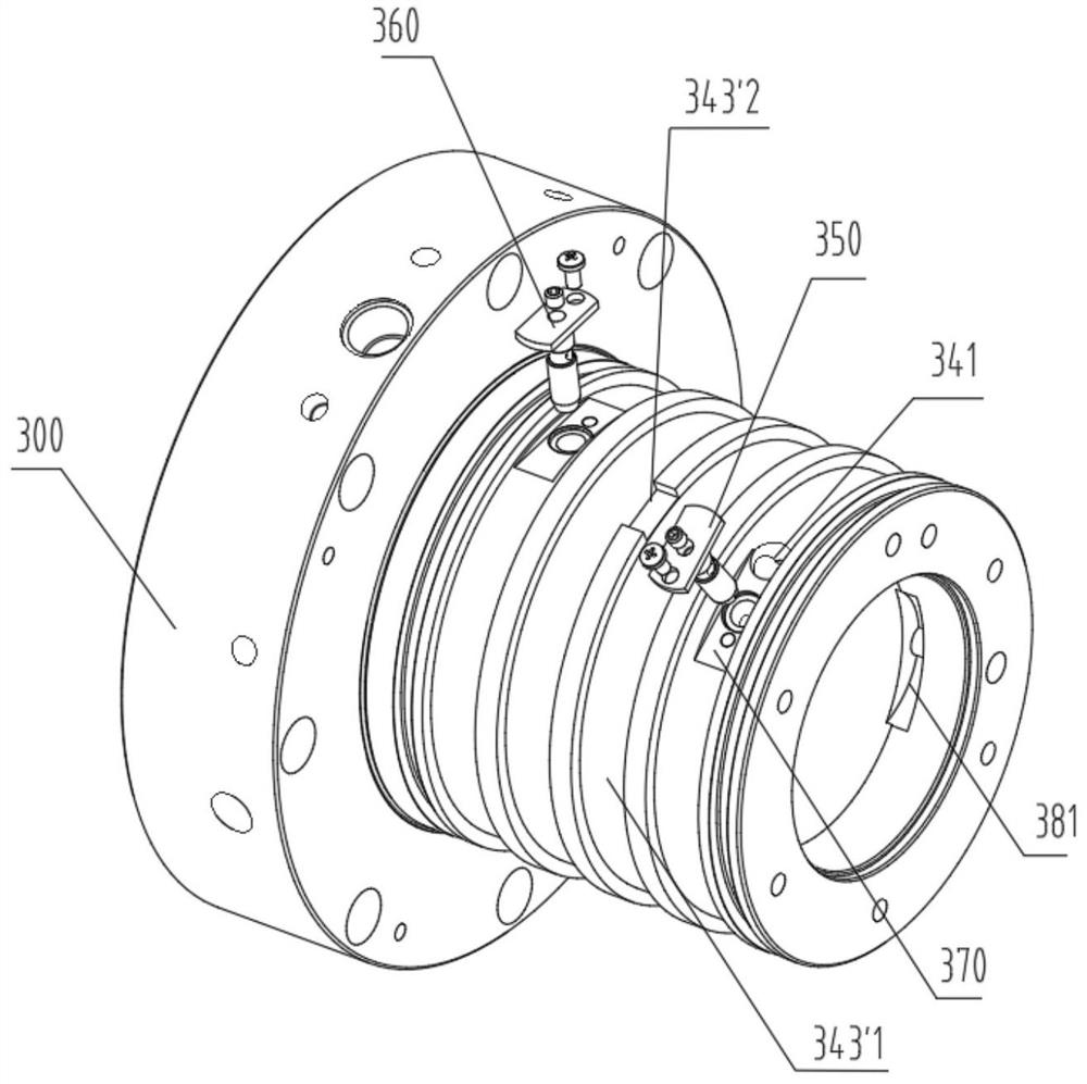
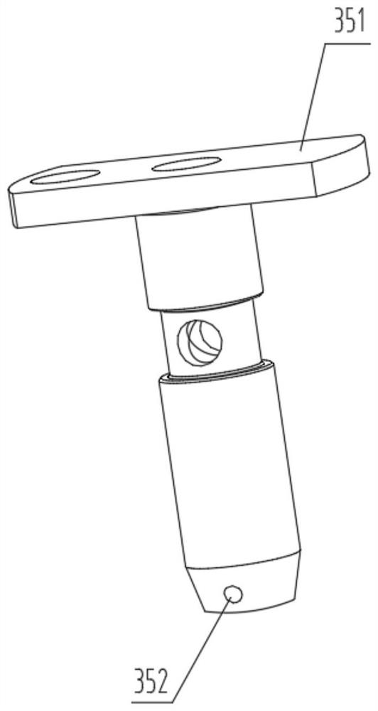
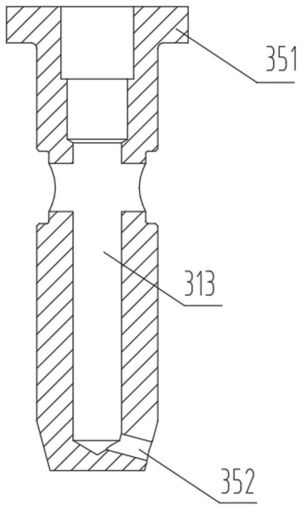
[0052] This solution provides a bearing seat and an electric spindle. The bearing seat 300 is installed on the motor spindle. The bearing seat 300 can cooperate with two bearings at the same time. The bearing seat 300 is provided with a first oil inlet passage 310, a second oil inlet passage 320, The oil return passage 330 and the coolin...


PUM


Abstract

The invention relates to the technical field of machine tools, in particular to a bearing seat and an electric main shaft; a first oil inlet path communicates to a first bearing mounting part of the bearing seat; a second oil inlet path communicates to a second bearing mounting part of the bearing seat; and an oil return path respectively communicates to the first bearing mounting part and the second bearing mounting part so as to facilitate the backflow of lubricating oil. According to the bearing seat, independent lubricating flow channels are respectively designed for a first bearing and asecond bearing, so that the accuracy of lubricating parameters is guaranteed, the heat generated in the working process of the bearings is reduced, and the service life of the bearings is prolonged; and cooling flow channels comprise a first flow channel positioned inside the bearing seat and a second flow channel formed in the outer periphery side of the bearing seat, the first flow channel communicates with the second flow channel, existing structural members for forming cooling flow channels are eliminated, and the cooling flow channels are formed in the bearing seat, so that the space occupation is reduced, and the outer diameter size of the front end of the electric main shaft is reduced.

Description

technical field [0001] The present application generally relates to the technical field of machine tools, and in particular, relates to a bearing seat and an electric spindle. Background technique [0002] The electric spindle has a transmission structure mode in which the built-in motor and the machine tool spindle are "combined into one". The bearing is the core of the electric spindle and its rotating support components. Its lubrication and cooling play a vital role in the rotation accuracy, processing quality and service life of the spindle. Important role, oil-air lubrication is to mix lubricating oil with compressed air, send it to the oil nozzle through the oil delivery pipe, and spray it out from the oil nozzle to the bearing. The cooling channel structure of most electric spindle bearings is axially Or radial inflow, so that the wall thickness of the entire sleeve is increased, and the wall thickness of the bearing seat connected to the sleeve at the front end of th...

Claims


Application Information

Patent Timeline
Patent Type & Authority Applications(China)
IPC IPC(8): F16C35/067F16C37/00F16N1/00F16J15/16
CPCF16C35/067F16C37/00F16J15/16F16N1/00
Inventor 邵启鹏耿继青何圳涛刘永连王攀
Owner GREE ELECTRIC APPLIANCES INC
Learn More