
Eureka
For R&D, Eureka makes reading and utilizing patents & technical documents easy.
Eureka AIR
Designed for self-driven R&D workflows. Generate viable solutions, solve complex R&D challenges, empower your innovation with AI.

Eureka Materials
Designed for material experts only. Revolutionize your material R&D, from search, analyze, to developing new materials.

TechResearch
Generate reliable direction feasibility study reports for your R&D in just a few steps.

TechSeek
Discover and master advanced knowledge NOW. Basics, ideas, possibilities, all at once.

TechMind
As an expert in R&D Theories, TechMind can generates customized viable solutions instantly.

TechRisk
Analyze your overall solution with one click, know your potential R&D risks in advance.

TechMonitor
Get weekly tech updates, stay abreast of the latest tech innovations and key insights.
Sludge sampling device
A sampling device and sludge technology, applied in the direction of sampling devices, sampling, measuring devices, etc., can solve the problems of increased process steps and easy mixing of sewage, etc., to achieve the effect of improving collection efficiency and improving work efficiency
- Summary
- Abstract
- Description
- Claims
- Application Information
AI Technical Summary
Problems solved by technology
Method used
Image


Examples
Embodiment 1
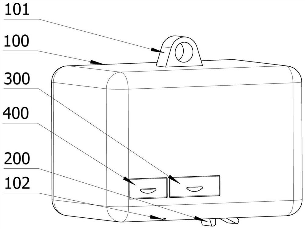
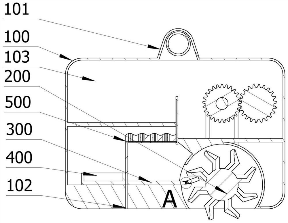
[0061] Such as figure 1 — Figure 5 As shown, a sludge sampling device includes: a main body 100 , a collection unit 200 , a sludge collection unit 300 , a sewage collection unit 400 , and a separation unit 500 . The main body 100 has: a suspension ring 101 and a first receiving space 103 . The suspension ring 101 is disposed above the main body 100 , and the suspension ring 101 is used to move the main body 100 up and down; the first accommodating space 103 is disposed in the main body 100 . The collecting part 200 is arranged in the first accommodation space 103 of the main body 100. The collecting part 200 is used to collect the mixture of sewage and sludge. The collecting part 200 has: a collecting part 201, a driving shaft 202, a driven shaft 203, a driving belt 204, A gear 205, a second gear 206, and a first motor 207. The collection part 201 is installed in the first accommodation space 103, the bottom of the collection part 201 passes through the first accommodation...
Embodiment 2
[0075] A sludge sampling method, comprising the steps of:
[0076] Placement, place the sludge sampling device in the sewage;
[0077] Sampling, the first motor 207 is started, thereby driving the second gear 206 to rotate, thereby driving the first gear 205 to rotate, thereby driving the drive shaft 202 to rotate, thereby driving the first connecting member 2021 arranged on the drive shaft 202 to rotate , so that the driving belt 204 matched with it is rotated, so that the second connecting part 2031 is rotated, thereby driving the driven shaft 203 to rotate, thereby driving the collecting part 201 to rotate, so that the sludge enters the collecting part 201 for collection;
[0078] Separation, when the sludge is sampled to a certain extent, the third motor 700 starts to drive the fourth gear 701 to rotate, thereby driving the isolation plate 505 to move downward, so that the isolation plate 505 isolates the sludge collection part 300, Afterwards, the second motor 600 starts...
PUM
 Abstract
Description
Claims
Application Information
 - R&D Engineer
- R&D Manager
- IP Professional
- Industry Leading Data Capabilities
- Powerful AI technology
- Patent DNA Extraction
Browse by: Latest US Patents, China's latest patents, Technical Efficacy Thesaurus, Application Domain, Technology Topic, Popular Technical Reports.
© 2024 PatSnap. All rights reserved.Legal|Privacy policy|Modern Slavery Act Transparency Statement|Sitemap|About US| Contact US: help@patsnap.com