Fuel cell unit
A fuel cell unit and fuel cell stack technology, applied in the direction of fuel cells, fuel cell components, power system fuel cells, etc., can solve the problems of increasing the size of fuel cell units, and achieve the effect of suppressing the size increase
- Summary
- Abstract
- Description
- Claims
- Application Information
AI Technical Summary
Problems solved by technology
Method used
Image
Examples
no. 1 approach
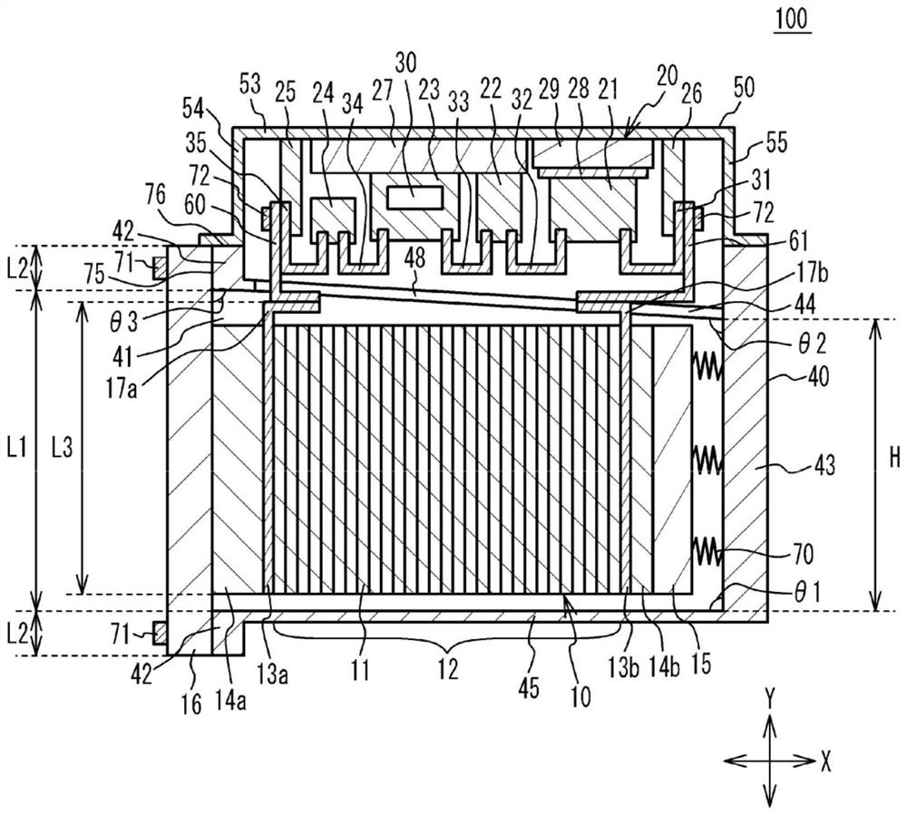
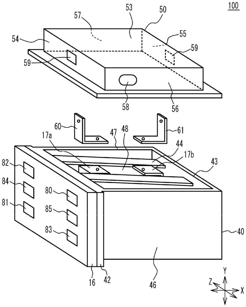
[0029] figure 1 is a sectional view of the fuel cell unit according to the first embodiment. figure 2 is an exploded perspective view of the fuel cell unit according to the first embodiment. Some components are shown in figure 1 The rear side of the paper without hatching. This also applies to Figure 4B to Figure 10 . Such as figure 1 and figure 2 As shown in , the fuel cell unit 100 according to the first embodiment includes a fuel cell stack 10 , an end plate 16 , a boost converter 20 , a stack case 40 , a converter case 50 , and bus bars 60 and 61 . Boost converter 20 is an example of a power converter. The converter case 50 is an example of a power converter case.
[0030] The fuel cell stack 10 includes a cell stack 12 , terminals 13 a and 13 b , insulators 14 a and 14 b , and a pressure plate 15 . The unit cells 11 of the battery stack 12 are stacked in the X direction. Terminals 13 a and 13 b are respectively provided at both ends of the battery stack 12 in...
no. 2 approach
[0065] Figure 8 is a sectional view of the fuel cell unit according to the second embodiment. Such as Figure 8 As shown in , with regard to the fuel cell unit 200 according to the second embodiment, in addition to the side wall 44 , the side wall 45 is inclined with respect to the bottom wall 43 . For example, the angle θ1 between the side wall 45 and the bottom wall 43 at the side of the fuel cell stack 10 is larger than 90 degrees. For example, the angle θ1 is approximately 92 degrees. In other words, when it is assumed that the side wall 45 extends to the end plate 16 , the angle θ4 between the side wall 45 at the side of the fuel cell stack 10 and the end plate 16 is about 88 degrees. The angle between the side wall 46 at the side of the fuel cell stack 10 and the bottom wall 43 is about 93 degrees. The angle between the side wall 47 at the side of the fuel cell stack 10 and the bottom wall 43 is about 93 degrees. The angle θ2 between the side wall 44 and the bottom...
no. 3 approach
[0069] Figure 9A is a sectional view of the fuel cell unit according to the third embodiment. Figure 9B is a cross-sectional view of some components of a boost converter housed in a converter housing. about Figure 9A and Figure 9B In the fuel cell unit 300 according to the third embodiment shown in , the reactor 21 , the current sensor 22 , the IPM 23 and the capacitor 24 of the boost converter 20 respectively have end portions at the side wall 44 side of the stack case 40 part. A distance L1 is defined between the bottom wall 53 of the converter case 50 and the end portion of the reactor 21 . A distance L2 is defined between the bottom wall 53 and the end portion of the current sensor 22 . A distance L3 is defined between the bottom wall 53 and the end portion of the IPM 23 . A distance L4 is defined between the bottom wall 53 and the end portion of the capacitor 24 . The distances L1 to L4 are different from each other. For example, the distance L1 between the en...
PUM
 Abstract
Description
Claims
Application Information
 - R&D Engineer
- R&D Manager
- IP Professional
- Industry Leading Data Capabilities
- Powerful AI technology
- Patent DNA Extraction
Browse by: Latest US Patents, China's latest patents, Technical Efficacy Thesaurus, Application Domain, Technology Topic, Popular Technical Reports.
© 2024 PatSnap. All rights reserved.Legal|Privacy policy|Modern Slavery Act Transparency Statement|Sitemap|About US| Contact US: help@patsnap.com


