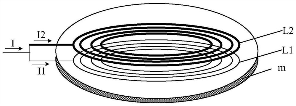
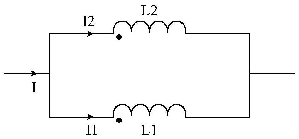
Coil module and electric energy transmitting circuit

A technology of coils and modules, which is applied in the direction of battery circuit devices, circuits, circuit devices, etc., can solve the problems of increasing costs and not being able to reduce losses, and achieve the effects of ensuring charging speed, reducing losses, and ensuring the degree of freedom of charging

Pending Publication Date: 2020-12-08
NINGBO WEIE ELECTRONICS TECH CO LTD
View PDF0 Cites 0 Cited by
  • Summary
  • Abstract
  • Description
  • Claims
  • Application Information

AI Technical Summary

Problems solved by technology

In order to reduce the loss of the coil, some existing technologies use thicker winding wires, but thicker non-standard wires will increase the cost
At the same time, due to the skin effect and proximity effect of high-frequency current, when the wire diameter of the winding wire increases to a certain extent, the loss cannot be reduced

Method used


Image

  • Coil module and electric energy transmitting circuit
  • Coil module and electric energy transmitting circuit
  • Coil module and electric energy transmitting circuit

Examples


Embodiment Construction

[0028] The present invention is described below based on examples, but the present invention is not limited to these examples. In the following detailed description of the invention, some specific details are set forth in detail. The present invention can be fully understood by those skilled in the art without the description of these detailed parts. In order not to obscure the essence of the present invention, well-known methods, procedures, procedures, components and circuits have not been described in detail.

[0029] Additionally, those of ordinary skill in the art will appreciate that the drawings provided herein are for illustrative purposes and are not necessarily drawn to scale.

[0030] Meanwhile, it should be understood that in the following description, "circuit" refers to a conductive loop formed by at least one element or sub-circuit through electrical connection or electromagnetic connection. When an element or circuit is said to be "connected to" another eleme...


PUM


Abstract

The embodiment of the invention discloses a coil module and an electric energy transmitting circuit. The coil module comprises at least two parallel branches, each parallel branch comprises a coil anda first capacitor which are connected in series, and the capacitance value of each first capacitor is set to reduce or eliminate the equivalent impedance difference between the parallel branches. Therefore, while the charging speed and the charging freedom degree are ensured, the loss is reduced, and the wireless charging efficiency is improved.

Description

technical field [0001] The present invention relates to the field of electronic power technology, specifically to the field of wireless charging, and more specifically to a coil module and a power transmitting circuit. Background technique [0002] Mobile terminals with wireless charging are becoming more and more popular. Most mobile terminals are equipped with wireless charging functions as standard, and users have higher and higher requirements for wireless charging speed and charging freedom. Therefore, the power transmitting coil in the wireless charger needs to pass through The larger the current, the stronger the magnetic field can be excited. In order to reduce the loss of the coil, some existing technologies use thicker winding wires, but thicker non-standard wires will increase the cost. At the same time, due to the skin effect and proximity effect of high-frequency current, when the wire diameter of the winding wire increases to a certain extent, the loss cannot ...

Claims


Application Information

Patent Timeline
Patent Type & Authority Applications(China)
IPC IPC(8): H02J50/10H02J50/12H02J7/00H01F38/14H01F27/40H01F27/34H01F27/28
CPCH02J50/10H02J50/12H02J7/0013H01F38/14H01F27/2871H01F27/40H01F27/34H01F27/366H02J50/70H02J50/402H01F27/36
Inventor 徐立智冯维一余峰
Owner NINGBO WEIE ELECTRONICS TECH CO LTD
Why Eureka
Try Eureka