
Water filtering and circulating equipment for drainage engineering, and working method thereof

A technology of circulation equipment and drainage engineering, applied in the field of drainage engineering, can solve the problems of sludge odor, filter equipment can not work continuously, and the surrounding environment is harsh, and achieve the effect of improving efficiency

Active Publication Date: 2020-12-11
SHANDONG BUSINESS INST
View PDF7 Cites 2 Cited by
  • Summary
  • Abstract
  • Description
  • Claims
  • Application Information

AI Technical Summary

Problems solved by technology

[0004] The purpose of the present invention is to solve the problem that in the prior art, after the filter equipment used is working, the silt still remains in the inside of the filter cartridge, and then, the staff needs to stop the filtering work intermittently, and clean the silt inside the filter cartridge for the next time. Filtering the water for the drainage project causes the filter equipment to not work in a continuous cycle, so as to achieve the effect of non-stop work on the water for the drainage project; after the water for the drainage project is filtered, the silt is directly piled up and stored, and the silt contains a large amount of water and cannot be processed. Moreover, a large amount of silt accumulation produces peculiar smell, which leads to the problem that the surrounding environment is relatively bad, and a kind of drainage engineering water filtration and circulation equipment and its working method are proposed

Method used


Image

  • Water filtering and circulating equipment for drainage engineering, and working method thereof
  • Water filtering and circulating equipment for drainage engineering, and working method thereof
  • Water filtering and circulating equipment for drainage engineering, and working method thereof

Examples


Embodiment Construction

[0032] The technical solutions of the present invention will be clearly and completely described below in conjunction with the embodiments. Apparently, the described embodiments are only some of the embodiments of the present invention, not all of them. Based on the embodiments of the present invention, all other embodiments obtained by persons of ordinary skill in the art without creative efforts fall within the protection scope of the present invention.

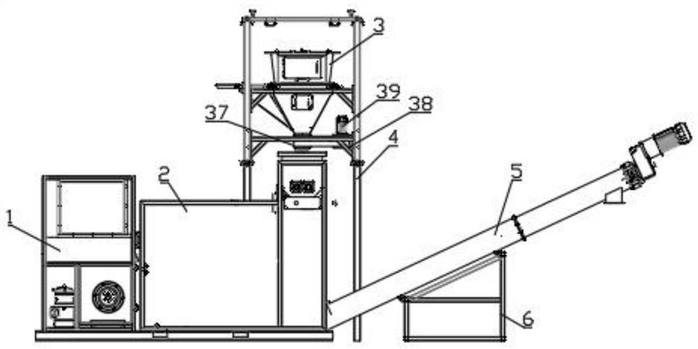
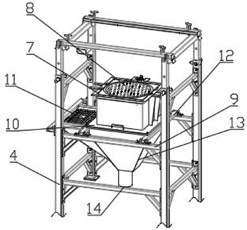
[0033] see Figure 1-7 As shown, a drainage engineering water filtration circulation equipment and working method thereof, including a condenser 1, a sludge drying mechanism 2, a filtering mechanism 3 and a delivery pipe 5;

[0034] The filter mechanism 3 is installed on the support frame 4, and a sludge drying mechanism 2 is arranged directly below the discharge end of the filter mechanism 3, and a condenser 1 is arranged on one side of the sludge drying mechanism 2, and is connected with the condenser 1, and the sludge A...


PUM


Abstract

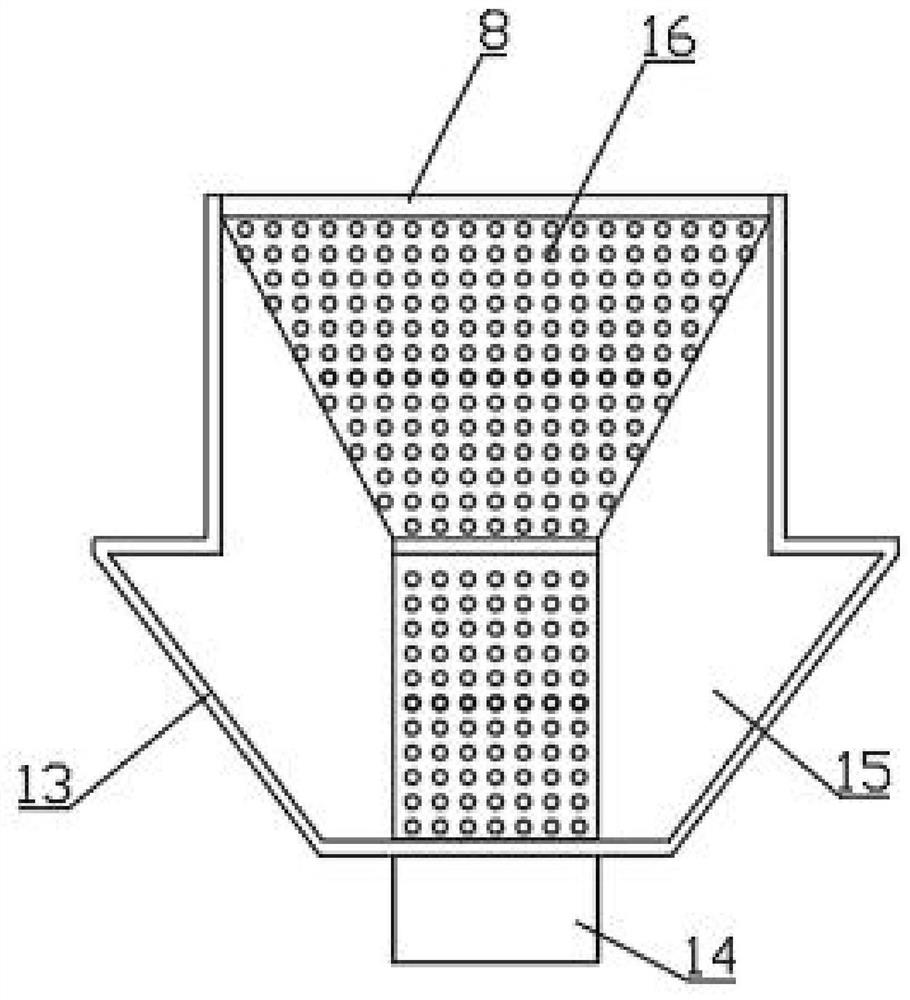
The invention discloses water filtering and circulating equipment for drainage engineering, and a working method thereof. The water filtering and circulating equipment comprises a condenser, a sludgedrying mechanism, a filtering mechanism and a conveying pipe, wherein the filtering mechanism is installed on a supporting frame, the sludge drying mechanism is arranged under the discharging end of the filtering mechanism, the condenser is arranged on one side of the sludge drying mechanism and connected with the condenser, the conveying pipe is arranged under the discharging end of the sludge drying mechanism, the top end of a centrifugal cylinder is rotatably connected with the top surface of a filter box, the bottom end of the centrifugal cylinder is connected with a sewage discharge pipe,the bottom end of the sewage discharge pipe extends out of a transfer box and is rotatably connected with the transfer box, a plurality of groups of filter holes are uniformly formed in the arc-shaped side wall of the centrifugal cylinder and the side wall of the sewage discharge pipe respectively, and a water storage bin is formed between the inner walls of the filter box and the transfer box and the outer wall of the centrifugal cylinder. The equipment of the invention has the advantages that water for drainage engineering is filtered through the centrifugal effect, so that the filtering efficiency is greatly improved, and filtered sludge can be automatically discharged.

Description

technical field [0001] The invention belongs to the technical field of drainage engineering, and relates to a filtration circulation equipment and a working method thereof, in particular to a drainage engineering water filtration circulation equipment and a working method thereof. Background technique [0002] Drainage engineering refers to the project of collecting and discharging human domestic sewage and various waste water in production, redundant surface water and groundwater (lowering the groundwater table). The main facilities include drainage ditches or pipelines at all levels and their ancillary buildings. Depending on different drainage objects and drainage requirements, water pumps or other water lifting machinery, sewage treatment buildings, etc. can also be added. Mainly used in farmland, mines, towns (including factories) and construction sites, etc. [0003] In the prior art, after the filter equipment is used, the sludge still stays in the inside of the filt...

Claims


Application Information

Patent Timeline
IPC IPC(8): B01D33/66B01D33/58B01D33/11
CPCB01D33/663B01D33/58B01D33/11
Inventor 耿玉丽
Owner SHANDONG BUSINESS INST
Learn More