
Pre-filter for flue gas analysis

A pre-filter and flue gas analysis technology, which is applied in the direction of dispersed particle filtration, analysis materials, instruments, etc., can solve the problems that the filter pipe is easily damaged by impact, the chassis is easily deformed, and the operating efficiency of flue gas analysis equipment is affected.

Inactive Publication Date: 2020-12-11
山东光测环境科技有限公司
View PDF7 Cites 0 Cited by
  • Summary
  • Abstract
  • Description
  • Claims
  • Application Information

AI Technical Summary

Problems solved by technology

[0003] 1. The front end of the flue gas analysis equipment in the prior art is equipped with a pre-filter to filter the dust in the flue gas. However, the inside of the case of this filter lacks an effective support structure. When the case is impacted by the outside, the case is easily deformed , the internal filter pipeline is easily damaged by impact, for this reason, we propose a pre-filter for flue gas analysis
[0004] 2. The front end of the flue gas analysis equipment in the prior art is equipped with a pre-filter, and when this filter is used for a long time, the filter element inside the filter needs to be replaced. The gas analysis equipment is shut down and replaced, which affects the operation efficiency of the flue gas analysis equipment. Therefore, we propose a pre-filter for flue gas analysis
[0005] 3. The front end of the flue gas analysis equipment in the prior art is provided with a pre-filter, which is provided with a simple filter element for filtering, and most of these filter elements are fixed inside the filter box by screw locking. It is necessary to remove the screws to disassemble the filter element in the filter box, which affects the replacement efficiency of the filter element inside the filter. Therefore, we propose a pre-filter for flue gas analysis

Method used


Image

  • Pre-filter for flue gas analysis
  • Pre-filter for flue gas analysis

Examples


Embodiment Construction

[0025] In order to make the purpose, technical solutions and advantages of the present invention clearer, the present invention will be further described in detail below in conjunction with the accompanying drawings. Obviously, the described embodiments are only some of the embodiments of the present invention, rather than all of them. Based on the embodiments of the present invention, all other embodiments obtained by persons of ordinary skill in the art without making creative efforts belong to the protection scope of the present invention.

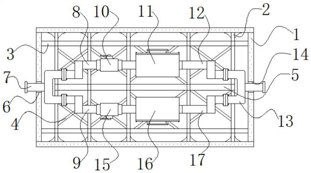
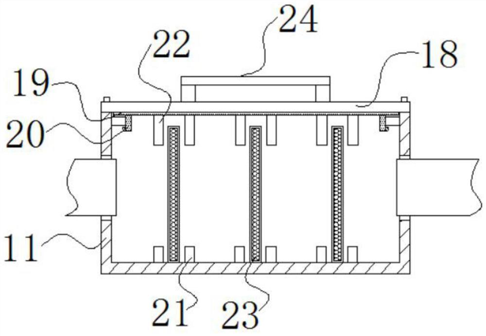
[0026] The following will combine Figure 1 ~ Figure 2 A pre-filter for flue gas analysis according to an embodiment of the present invention is described in detail.

[0027] refer to figure 1 and figure 2As shown, a pre-filter for flue gas analysis provided by the embodiment of the present invention includes a cabinet 1, the inner wall of the cabinet 1 is welded with a lining rod A2 and a lining rod B3, and the lining rod A2 and the...


PUM


Abstract

The invention discloses a pre-filter for flue gas analysis, and belongs to the technical field of flue gas analysis; the pre-filter comprises a case, a lining rod A and a lining rod B are welded on the inner wall of the case and are welded into an inner supporting frame body in the case, and a middle rod is welded in the middle of the inner supporting frame body formed by welding the lining rod Aand the lining rod B; an X-shaped supporting rod is welded between the lining rod A and the lining rod B on the two sides of the middle rod, a through hole A is formed in one side of the outer wall ofthe case, an air inlet pipeline of a three-way pipe A extends out of the through hole A, the lining rod A and the lining rod B are welded in the case to form the inner supporting frame body, and themiddle rod is arranged in the middle of the inner supporting frame body for supporting. Meanwhile, the X-shaped supporting rod is welded between the lining rod A and the lining rod B on the two sidesof the middle rod, a reinforced supporting structure is provided for the interior of the case through welding of multiple sets of rod bodies, and the internal structure of the case is reinforced.

Description

technical field [0001] The invention relates to the technical field of flue gas analysis, in particular to a pre-filter for flue gas analysis. Background technique [0002] The flue gas analyzer is a device that uses electrochemical sensors to continuously analyze and measure the flue gas content of CO2, CO, NOx, SO2, etc. It is mainly used for hand-held use of small fuel oil and gas boiler pollution discharge or environmental monitoring near pollution sources. According to the way of use, it can be divided into handheld flue gas analyzers and fixed connection recording flue gas analyzers. [0003] 1. The front end of the flue gas analysis equipment in the prior art is equipped with a pre-filter to filter the dust in the flue gas, but the inside of the case of this filter lacks an effective support structure. When the case is impacted by the outside, the case is easily deformed , the internal filter pipeline is easily damaged by impact, for this reason, we propose a pre-fi...

Claims


Application Information

Patent Timeline
Patent Type & Authority Applications(China)
IPC IPC(8): B01D46/00B01D46/12G01N27/26G01N33/00
CPCB01D46/0005B01D46/12G01N33/0011G01N27/26B01D2258/0283B01D46/62
Inventor 任东发李树震师圆生李杨
Owner 山东光测环境科技有限公司
Learn More