Short-stress rolling mill capable of automatically adjusting prestress of roll gaps

A short stress rolling mill, automatic adjustment technology, applied in the direction of metal rolling stand, metal rolling mill stand, metal rolling, etc., can solve the problems of large size deviation, change of roll gap distance, and inability to maintain constant prestress, etc. Achieve the effect of large rolling force and effective control of product precision

Pending Publication Date: 2020-12-11
SHENYANG DALU LASER TECH
View PDF0 Cites 0 Cited by
  • Summary
  • Abstract
  • Description
  • Claims
  • Application Information

AI Technical Summary

Problems solved by technology

[0003] Before the rolling mill is rolled, it is necessary to pre-set the distance between the rolls according to the size of the profile. Since there is a gap between the parts of the rolling mill, when the roller presses the parts, the gap between the parts of the rolling mill will change. , the superposition of multiple changes will cause the distance of the roll gap to change, the error will increase, and the product size will easily exceed the specified range.
[0004] In order to avoid the above problems, it is necessary to prestress the rolls in advance, that is, a prestressed rolling mill appears. The prestressed rolling mill usually uses elastic materials to provide prestressing for the rolls, thereby eliminating the gap between each workpiece. However, due to the elasticity The change of force caused by the change of material size can not keep the prestress constant
[0005] At the same time, during the continuous operation of the rolling mill, the roll gap will change under the action of wear and tear, resulting in a large size deviation between the initial product and the final product, and the product accuracy cannot be accurately controlled; and, in the process of use, once the roll If the seam distance is out of tolerance, the production must be stopped and the rolling mill replaced

Method used


Image

  • Short-stress rolling mill capable of automatically adjusting prestress of roll gaps

Examples


Embodiment Construction

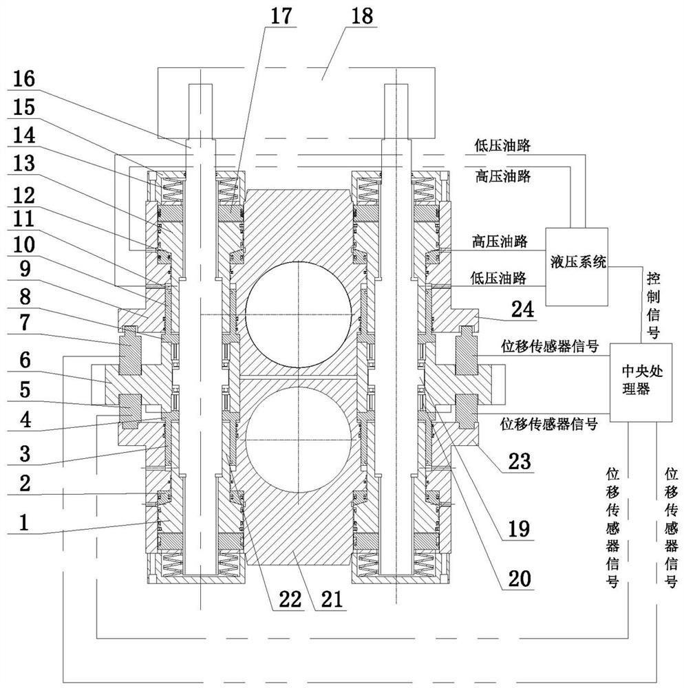
[0017] The present invention comprises that the pull rod 16 is axially fixedly arranged in the frame body 6, the upper and lower sides of the frame body 6 are respectively provided with an upper roller box 9 and a lower roller box 21, and the upper roller box 9 is an upper main nut 13, Inside the lower roll box 21 is the lower main nut 1, and the upper main nut 13 and the lower main nut 1 are connected to the pull rod 16 through positive and negative threads. It is characterized in that: the upper part of the upper roller box 9 and the lower part of the upper main nut 13 Between, and between the lower part of the lower roller box 21 and the upper part of the lower main nut 1, a main oil chamber 12 is arranged, and the oil return of the main oil chamber 12 is arranged between the tie rod 16 and the upper roller box 9, and the lower roller box 21 Disc spring 14; the frame body 6 is provided with a prestressing system of pull rod 16 and a real-time monitoring system for the distan...


PUM


Abstract

The invention belongs to the technical field of steel rolling equipment, particularly relates to an improvement of a short-stress rolling mill structure, and provides a short-stress rolling mill whichis capable of automatically adjusting the prestress of roll gaps, and is high in machining precision and high in production efficiency. The short-stress rolling mill comprises a pull rod arranged ina rack body and axially fixed, wherein an upper roller box and a lower roller box are arranged on the upper side and the lower side of the rack body respectively; an upper main nut is arranged in theupper roller box; a lower main nut is arranged in the lower roller box; and the pull rod is connected between the upper main nut and the lower main nut through right-hand threads and left-hand threads. The short-stress rolling mill is characterized in that main oil cavities are formed between the upper part of the upper roller box and the lower part of the upper main nut and between the lower partof the lower roller box and the upper part of the lower main nut, and oil return disc springs of the main oil cavities are arranged between the pull rod and the upper roller box and between the pullrod and the lower roller box; and a prestress system of the pull rod and a real-time roller box distance monitoring system are arranged on the rack body.

Description

technical field [0001] The invention belongs to the technical field of steel rolling equipment, and in particular relates to an improvement of the structure of a short stress rolling mill. Background technique [0002] In the existing short-stress rolling mill, the upper and lower roll boxes, spherical pads, main nuts, and tie rods constitute the stress loop. Since the stress line of this type of rolling mill is much shorter than that of the frame-type rolling mill, it is called Short stress rolling mill, short stress rolling mill is mainly used in the production of small profiles. [0003] Before the rolling mill is rolled, it is necessary to pre-set the distance between the rolls according to the size of the profile. Since there is a gap between the parts of the rolling mill, when the roller presses the parts, the gap between the parts of the rolling mill will change. , The superimposition of multiple changes will cause the distance of the roll gap to change, the error wi...

Claims


Application Information

Patent Timeline
Patent Type & Authority Applications(China)
IPC IPC(8): B21B31/32
CPCB21B31/32
Inventor 李运强韩红凤郭建华周颖张岩刘豫
Owner SHENYANG DALU LASER TECH
Why Eureka
Try Eureka