Railway vehicle brake fusion control system and method

A technology that integrates control and rail vehicles. It is used in electric braking systems, railway vehicles, and vehicle components. It can solve the problems of motor vehicles that do not consider traction, the safety level needs to be improved, and the data delay is not completely solved. Redundancy, avoiding data interaction, eliminating the effect of data latency

Active Publication Date: 2020-12-11
CRRC QINGDAO SIFANG ROLLING STOCK RES INST
View PDF5 Cites 6 Cited by
  • Summary
  • Abstract
  • Description
  • Claims
  • Application Information

AI Technical Summary

Problems solved by technology

[0005] The purpose of the embodiment of the present invention is to provide a rail vehicle brake fusion control system and method to solve the problem that the hybrid braking in the prior art cannot be executed accurately, th

Method used


Image

  • Railway vehicle brake fusion control system and method
  • Railway vehicle brake fusion control system and method
  • Railway vehicle brake fusion control system and method

Examples


Embodiment Construction

[0047] The application will be further described in detail below in conjunction with the accompanying drawings and embodiments. It should be understood that the specific embodiments described here are only used to explain related inventions, rather than to limit the invention. It should also be noted that, for the convenience of description, only the parts related to the related invention are shown in the drawings.

[0048] It should be noted that, in the case of no conflict, the embodiments in the present application and the features in the embodiments can be combined with each other. The present application will be described in detail below with reference to the accompanying drawings and embodiments.

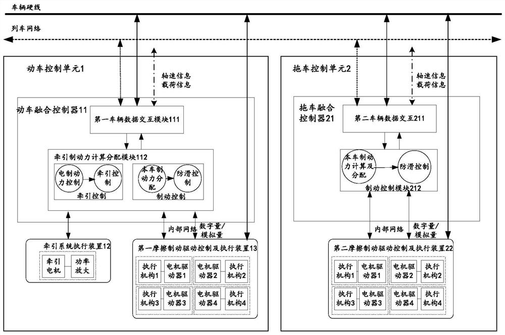
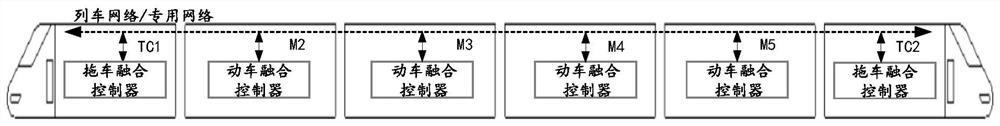
[0049] figure 1 It is a schematic structural diagram of the rail vehicle brake fusion control system provided by the embodiment of the present invention, figure 2 It is a schematic diagram of the whole vehicle provided by Embodiment 1 of the present invention. combine fi...


PUM


Abstract

The invention provides a railway vehicle brake fusion control system and method. The railway vehicle brake fusion control system comprise a bullet train control units and trailer control units. Each bullet train control unit comprises a bullet train fusion controller which receives a traction force instruction and carries out traction force calculation according to a preset first condition, or receives a brake instruction and carries out total brake force calculation according to the brake instruction, calculates electric brake force and first friction brake force according to a preset secondcondition, a traction system executing device used for executing traction operation according to traction force or executing brake operation according to the electric brake force, and a first frictionbrake driving control and executing device used for executing friction braking operation according to the first friction brake force. Each trailer control unit comprises a trailer fusion controller for receiving a brake instruction and calculating second friction brake force according to a preset third condition, and a second friction brake driving control and execution device for executing friction brake operation according to the second friction brake force. Therefore, the fusion control over traction and brake is completed.

Description

technical field [0001] The invention relates to the technical field of automatic control, in particular to a rail vehicle brake fusion control system and method. Background technique [0002] The current traction control system and brake control system of rail transit vehicles are two independent systems, each with its own independent controller. When the vehicle is braking, it will adopt the hybrid braking method of electric braking and friction braking to reduce the wear of the brake shoes. Generally, electric braking is used first, and the insufficient part of electric braking is supplemented by friction braking, so traction The system and the braking system will be controlled in cooperation. At present, the controllers between the two systems exchange information through the network. Due to the delay in the data transmission process, the hybrid braking cannot be accurately executed, which affects the braking response speed, resulting in electric braking and friction bra...

Claims


Application Information

Patent Timeline
IPC IPC(8): B60L7/26
CPCB60L7/26B60L2200/26
Inventor 苗峰骆凯张润泽吕艳宗
Owner CRRC QINGDAO SIFANG ROLLING STOCK RES INST
Why Eureka
Try Eureka