
Portable efficient drinking water preparation equipment

A high-efficiency, drinking water technology, used in water/sewage treatment equipment, water/sewage treatment, heating water/sewage treatment, etc., can solve the problems of time-consuming, inconvenient to carry and use water purifiers, and reduce sedimentation. , light weight, easy to carry

Inactive Publication Date: 2020-12-11
胡树斌
View PDF0 Cites 1 Cited by
  • Summary
  • Abstract
  • Description
  • Claims
  • Application Information

AI Technical Summary

Problems solved by technology

[0004] The purpose of the present invention is to solve the problem that in the prior art field surveys often require local water intake, but the common water intake method needs to spend a lot of time to filter the collected water again after collecting the water, and the common water purifier is not easy to carry And the shortcomings of use, and proposed a portable and efficient drinking water production equipment

Method used


Image

  • Portable efficient drinking water preparation equipment
  • Portable efficient drinking water preparation equipment
  • Portable efficient drinking water preparation equipment

Examples


Embodiment 1

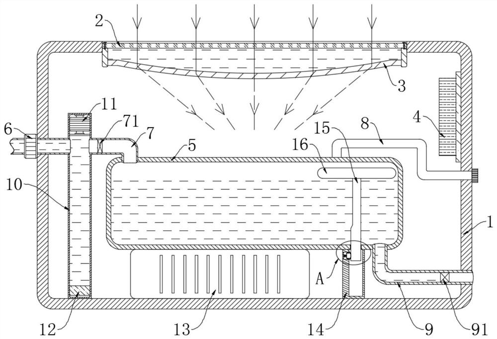
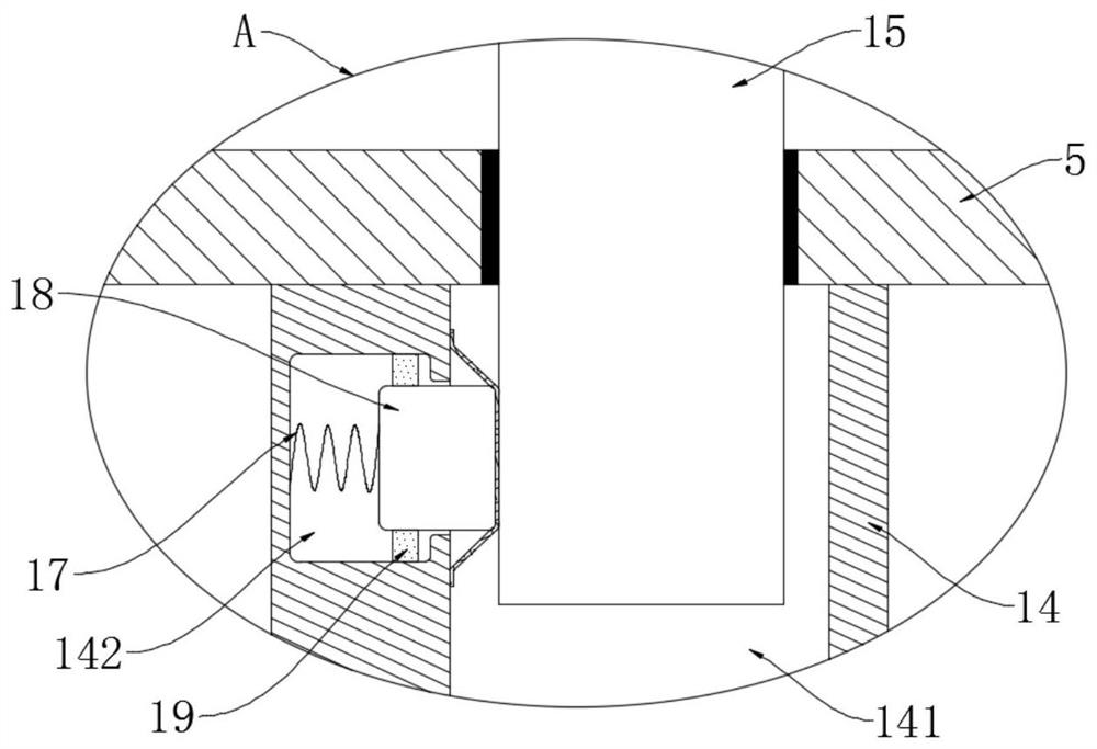
[0023] refer to Figure 1-2 , a portable high-efficiency drinking water production equipment, including a shock absorbing box 1, the wall of the shock absorbing box 1 is divided into two layers, the inner layer of the box wall is a hard box, and the outer layer is an elastic box with high toughness Body, between the inner layer and the outer layer is filled with lightweight shock-absorbing materials, such as sponges, air columns, etc., which can make the equipment more durable. The top wall of the shock-absorbing box 1 is provided with an installation opening, and a high The transparent flat plate 2 and the high transparent concave plate 3 are fixedly installed under the high transparent flat plate 2. When the gap between the high transparent concave plate 3 and the high transparent flat plate 2 is filled with clear water, this part forms a convex lens, which plays the role of concentrating light. Both the transparent plate 2 and the highly transparent concave plate 3 are made...

Embodiment 2

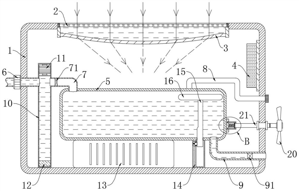
[0033] refer to Figure 3-4 The difference between this embodiment and Embodiment 1 is that: the side wall of the cushioning box 1 is provided with a rotating rod 21 through a one-way bearing, and the two ends of the rotating rod 21 are respectively connected with a fan 20 and a pinch plate 22, and the pinch plate The outer side of 22 is clamped with a drum 23, and the end of the drum 23 away from the pinch plate 22 is movably connected with a friction plate 25 through a plurality of short shafts. 22 is fixedly connected with the second spring 24.

[0034] This embodiment can explain its functional principle through the following operation mode: when the evaporation box 5 receives concentrated light, the fan 20 also rotates under the action of external wind force, and the rotating rod 21 drives the friction plate 25 to rotate through the pinch plate 22 and the rotating drum 23 , so that the friction between the friction plate 25 and the outer wall of the evaporation box 5 gen...


PUM


Abstract

The invention discloses portable efficient drinking water preparation equipment which comprises a shock absorption box, a mounting opening is formed in the top wall of the shock absorption box in a penetrating mode, a high-transmittance flat plate is fixedly arranged in the mounting opening, a high-transmittance concave plate is fixedly arranged below the high-transmittance flat plate, and an evaporation box is arranged in the shock absorption box; the evaporation box is connected with a liquid inlet mechanism and a liquid discharge mechanism, a liquid collecting pipe is communicated with theupper portion of the evaporation box, the end, away from the evaporation box, of the liquid collecting pipe extends out of the shock absorption box, and a photovoltaic assembly and a storage battery pack are further fixedly installed in the shock absorption box. The portable efficient drinking water preparation equipment is simple in structure and convenient to carry, drinking water can be prepared at a relatively constant rate, the workload of people can be greatly reduced, and the water preparation efficiency is greatly improved.

Description

technical field [0001] The invention relates to the technical field of water treatment equipment, in particular to a portable high-efficiency drinking water preparation equipment. Background technique [0002] Researchers in different fields often need to go outdoors to obtain accurate data or complete specimens. When going deep into uninhabited areas, they not only need to consider the dangers brought by the creatures in nature, but also need to consider the problem of supply. Drinking water is difficult. Compression, high demand, difficult to carry in large quantities, many areas do not have transportation conditions, research teams usually can only find water sources locally, and fetch water locally. [0003] There are many ways to get water in the wild, such as using transpiration to get water, collecting dew in the early morning, looking for areas where cumulonimbus clouds are located to collect precipitation, etc. The above water taking methods are all random, and it t...

Claims


Application Information

Patent Timeline
Patent Type & Authority Applications(China)
IPC IPC(8): C02F1/04
CPCC02F1/048C02F2201/002C02F2201/007
Inventor 胡树斌刘小莉
Owner 胡树斌
Learn More