Radio base station for CDMA mobile communication system

A technology of radio channel and radio base station, applied in the field of radio base station

Inactive Publication Date: 2003-09-03
FUJITSU LTD
View PDF0 Cites 0 Cited by
  • Summary
  • Abstract
  • Description
  • Claims
  • Application Information

AI Technical Summary

Problems solved by technology

[0013] Therefore, according to the above-mentioned method of setting the maximum number of radio channels Nrmax that can be allocated, the resources of the radio channels cannot be effectively utilized to the limit.

Method used


Image

  • Radio base station for CDMA mobile communication system
  • Radio base station for CDMA mobile communication system
  • Radio base station for CDMA mobile communication system

Examples


Embodiment Construction

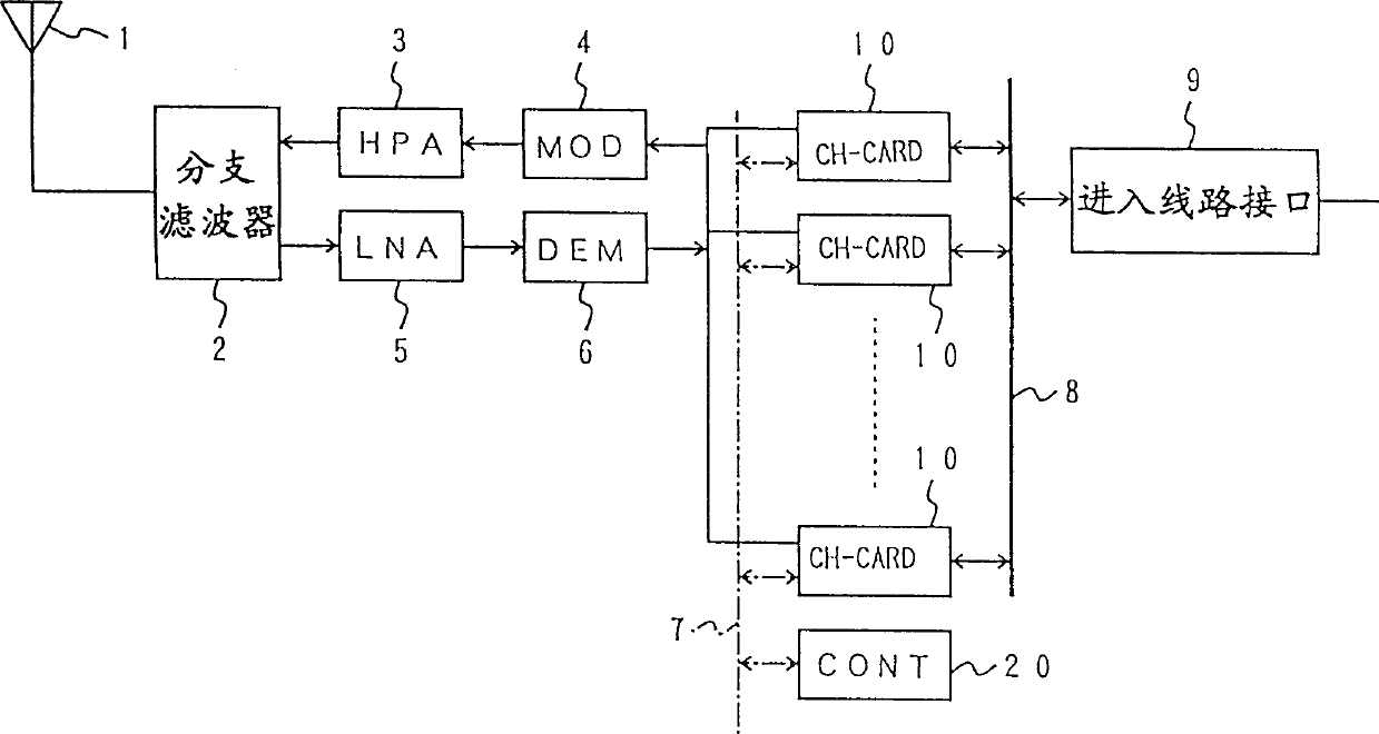
[0034] Fig. 1 is a system block diagram showing a radio base station for a CDMA mobile communication system. The radio base station comprises an antenna 1, a branch filter 2, a high power amplifier (HPA) 3, a modulator (MOD) 4, a low noise amplifier 5, a demodulator (DEM) 6, a control bus 7, A data communication bus 8, an incoming line interface 9, various channel cards (CH-CARD) 10 and a control unit (CONT) 20, their connections are shown in FIG. 1 .

[0035] One channel card 10 supplies a plurality of radio channels. Each channel card 10 is connected to an incoming line interface 9 via a data communication bus 8 . Further, each channel card is also connected to the control unit 20 through the control bus 7 . Each channel card 10 is also connected to a modulator 4 and a demodulator 6 . A radio channel is assigned to one of the channel cards 10 by the control unit 20 via the control bus 7 . The control unit 20 includes a storage section and a control section. The storage ...


PUM


Abstract

A radio base station in a CDMA mobile communication system for allocating radio channels to mobile stations at a plurality of different bit rates. The base station including a storage part for storing a maximum number of radio channels that makes a signal-to-interference noise power ratio for each channel greater than a predetermined value. The maximum number having a value which changes in steps depending on a bit rate used for a call presently made.

Description

technical field [0001] The present invention relates generally to radio base stations, and more particularly to a radio base station for a CDMA (Code Division Multiple Access) mobile communication system, which radio base station is capable of operating at a plurality of different bit rates using the CDMA transmission technique. emission. Background technique [0002] According to the CDMA transmission technique, a signal is first subjected to spreading processing with an assigned code, and then it is transmitted. Unlike the FDMA transmission technique and the TDMA transmission technique, the CDMA transmission technique is tolerant of interference from other radio channels, and communication can be carried out as long as these interferences do not exceed a predetermined permissible target line quality value. The line quality is determined by a ratio "(Eb / No)", where Eb is the signal power per single message and No is the noise power. [0003] The noise power No mainly cons...

Claims


Application Information

Patent Timeline
IPC IPC(8): H04J13/00H04L1/00H04W16/02H04W28/00H04W28/04H04W72/04H04W72/08H04W76/02H04W84/12H04W88/08
CPCH04L1/0002H04L1/0017H04W72/082H04W72/08H04B2201/709709H04W88/08H04W72/085H04W28/04H04W72/54H04W72/541H04W72/542H04W72/04H04B7/155
Inventor 熊谷佳晶信安康助
Owner FUJITSU LTD
Why Eureka
Try Eureka